


66
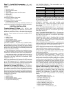
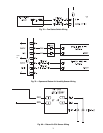
Table 27 — SGC Thermistor Designations
SGC — Staged Gas Controller
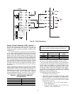
Step 20 — Install Optional Motormaster
®
V
Control — The Motormaster V control is a motor speed
control device which adjusts condenser fan motor speed in re-
sponse to varying liquid refrigerant pressure. A properly applied
Motormaster V control extends the operating range of air-condi-
tioning systems and permits operation at lower outdoor ambient
temperatures.
The optional Motormaster V controls are factory-installed.
Field-fabricated and installed wind baffles are also required for
units in areas with prevailing winds of more than 5 mph and
where temperatures drop below 32 F. The Motormaster V con-
trol permits operation of the unit to an ambient temperature of
–20 F. The control regulates the speed of one or two 3-phase fan
motors depending on unit size. Replacement of the fan motor on
most units is not necessary.
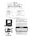
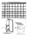
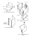
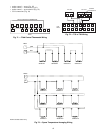
INSTALL FIELD-FABRICATED WIND BAFFLES
On size 040-060 units, in areas with prevailing winds of
more than 5 mph and where temperatures drop below 32 F,
wind baffles must be field fabricated to ensure proper cooling
cycle operation at low-ambient temperatures with Motormaster
V controls. Wind baffles are not needed on size 030, 035, and
070-100 units. See Fig. 70 for baffle details. Use 20-gage galva-
nized sheet metal, or similar corrosion-resistant material for the
baffles. Use field-supplied screws to attach baffles to unit.
Screws should be
1
/
4
-in. diameter or larger. Screws should not
be more than
1
/
2
-inch in length. Drill required screw holes for
mounting baffles.
THERMISTOR
PIN
CONNECTION
POINT
FUNCTION AND LOCATION
PART NO.
Thermistors
SAT1 J8 – 1,2 (SGC)
Supply-Air Thermistor (SAT) — Inserted into supply section
underneath the gas heat section (factory-provided,
field-installed)
HH79NZ033
SAT2 J8 – 3,4 (SGC)
Supply-Air Thermistor (SAT) — Inserted into supply section
underneath the gas heat section (factory-provided,
field-installed)
SAT3 J8 – 5,6 (SGC)
Supply-Air Thermistor (SAT) — Inserted into supply section
underneath the gas heat section (factory-provided,
field-installed)
LIMTTEMP J8 – 15,16 (SGC)
Limit Switch Thermistor (LIMTTEMP) — Inserted next the
lower limit switch (factory-installed)
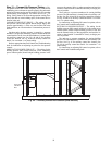
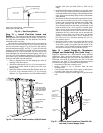
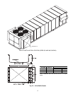
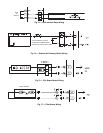
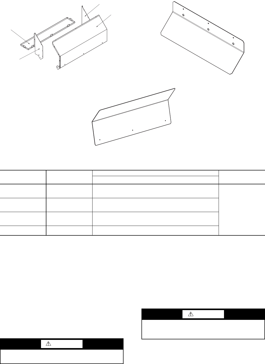
INLET
HOOD
INLET HOOD
SIDE
INLET HOOD
SIDE
SCREEN
(WITH SPEED CLIPS)
a48-8473
Fig. 67 — Inlet Hood Assembly (30-in.)
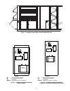
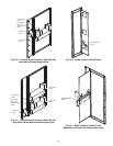
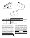
Fig. 68 — Air Baffle (14-in.)
Fig. 69 — Air Baffle (30-in.)
a48-8591
a48-8590
WARNING
To avoid the possibility of electrical shock, open all discon-
nects before installing or servicing this accessory.
CAUTION
To avoid damage to refrigerant coils, electrical compo-
nents, and wiring use extreme care when drilling screw
holes and screwing in fasteners.