


9
Step 9 — Install Duct Connections
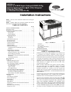
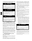
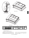
The unit has duct flanges on the supply -- and return-- air openings
on the side and bottom of the unit. For downshot applications, the
ductwork connects to the roof curb (See Fig. 2 and 3 for
connection sizes and locations).
Configuring Units for Downflow (Vertical) Discharge
ELECTRICAL SHOCK HAZARD
Failure to follow this warning could result in personal injury
or death.
Before installing or s ervicing system, always turn off main
power to system and install lockout tag. There may bemore
than one disconnect switch.
!
WARNING
1. Open all electrical disconnects before starting any service
work.
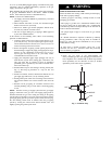
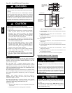
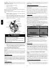
2. Remove horizontal (metal) duct covers to access vertical
(downflow) discharge duct knockouts in unit basepan. (See
Fig. 8.)
PROPERTY DAMAGE HAZARD
Failure to follow this caution m ay result in property damage.
Collect ALL screws that were removed. Do not leave s crews
on rooftop as permanent damage to the roof may occur.
CAUTION
!
To remove downflow return and supply knockout covers, break
front and right side connecting tabs with a screwdriver and
hammer. Push cover down to break rear and l eft side tabs.
NOTE: These panels are held in place with tabs similar to a n
electrical knockout. Reinstall horizontal duct covers (Fig. 8)
shipped on unit from factory. Insure openings are air and
watertight.
NOTE: The design and installation of the duct system must be in
accordance with the standards of the NFPA for installation of
nonresidence--type air conditioning and ventilating systems, NFP A
90A or residence--type, NFPA 90B; and/or local codes and
ordinances.
Adhere to the following criteria when selecting, sizing, and
installing the duct system:
1. Units are shipped for horizontal duct installation (by
removing duct covers).
2. Select and size ductwork, supply--air registers, and
return--air grilles according t o American Society of Heating,
Refrigeration and Air Conditioning Engineers (ASHRAE)
recommendations.
3. Use f lexible transition between rigid ductwork and unit to
prevent transmission of vibration. The transition may be
screwed or bolted to duct flanges. Use suitable gaskets to
ensure weather tight and airtight seal.
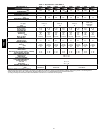
4. All units must have field--supplied filters or accessory filter
rack installed in the return--air side of the unit.
Recommended sizes for filters are shown i n Table 1.
5. Size all ductwork for maximum required airflow (either
heating or cooling) for unit being installed. Avoid abrupt
duct size increases or decreases or performance may be
affected.
6. Adequately insulate and weatherproof all ductwork located
outdoors. Insulate ducts passing through unconditioned
space, and use vapor barrier in accordance with latest issue
of Sheet Metal and Air Conditioning Contractors National
Association (SMACNA) and Air Conditioning Contractors
of America (ACCA) minimum installation standards for
heating and air conditioning systems. Secure all ducts to
building s tructure.
7. Flash, weatherproof, and vibration-- isolate all openings in
building structure in accordance with local codes and good
building practices.
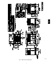
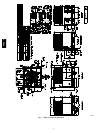
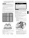
Horizontal Duct Covers
A09061
Basepan
Downflow
(Vertical)
Supply
Knockout
Basepan
Downflow
(Vertical)
Return
Knockout
A09060
Fig. 8 -- Supply and Return Duct Opening
48EZ --A