


40
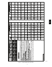
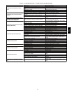
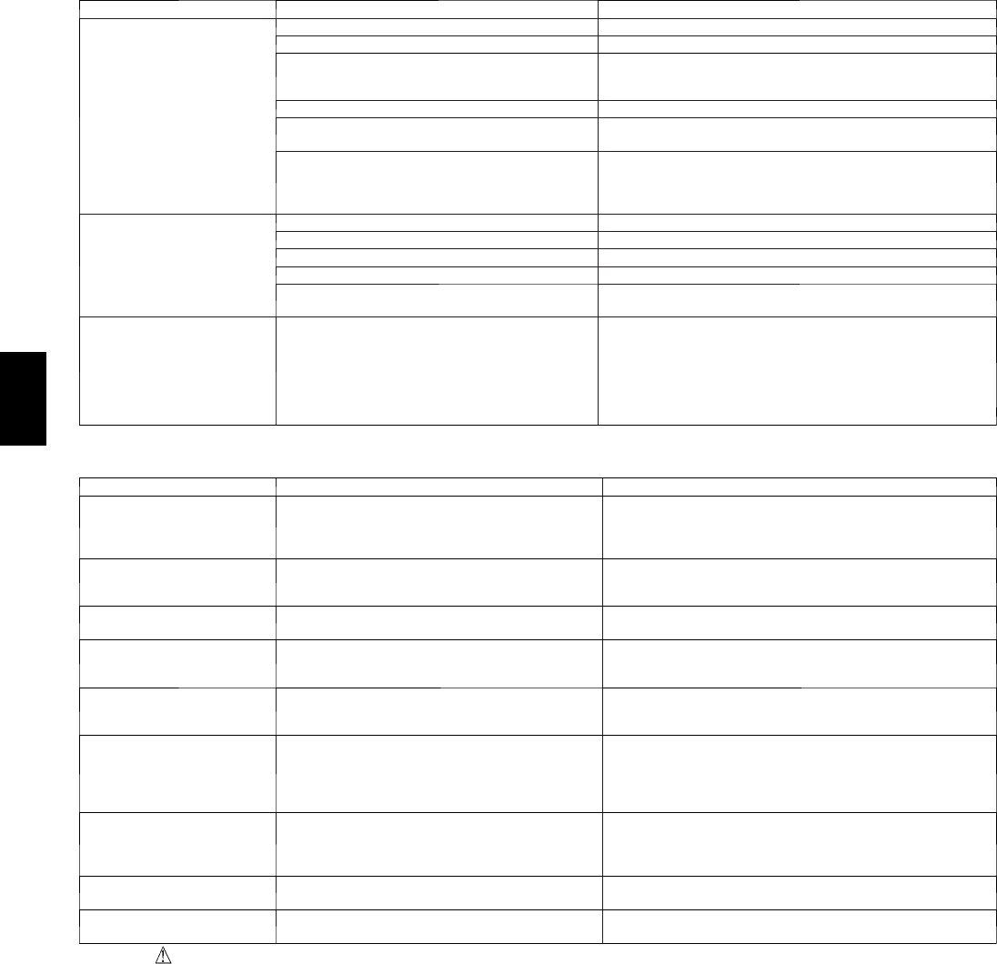
Table 13 – Troubleshooting Guide–Heating
SYMPTOM CAUSE REMEDY
Burners will not ignite
Water in gas line Drain. Install drip leg.
No power to furnace Check power supply fuses, wiring or circuit breaker.
No 24--v power supply to controlcircuit
Check transformer.
NOTE:Some transformers have internal over--current protection
that requires a cool--down period to reset.
Mis--wired or loose connections Check all wiringand wire nut connections
Misaligned spark electrodes
Check flame igniti onand sense electrode positioning.
Adjust as necessary.
No gas at main burners
1. Check gas line f or air. P urge as necessary. NOTE:After purging
gas line of air,wait at least 5 minutes for any gas to dissipate be-
fore attempting tolight unit.
2. Check gas valve.
Inadequate heating
Dirty air filter Clean or replace fi lter as necessary
Gas input to furnace too low Check gas pressure atmanifold match withthat onunit nameplate
Unit undersized for application Replace with proper unitor add additional unit
Restricted airflow Clean or replace fi lter. Remove any restriction.
Limitswitch cycles mainburners
Check rotationof blower, temperature rise of unit. Adjust as neces-
sary.
Poor flame characteristics
Incomplete combustion results in: Aldehyde odors,
carbon monoxi de,sooting f lame, floating flame
1. Tighten al lscrews around burner compartment
2. Cracked heatexchanger. Replace.
3. Unit over--fired. Reduce input (change orifices or adjust gas line
or manifold pressure).
4. Check burner alignment.
5. Inspect heat exchanger for blockage. Clean as necessary.
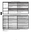
Table 14 – Troubleshooting Guide–LED Error Codes
SYMPTOM CAUSE REMEDY
No Power or Hardware fail-
ure
(LEDOFF)
Loss of power to control module(IGC)*.
Check 5--amp fuse son IGC*, power tounit, 24--v circuit breaker,
and transformer. Units without a24--v circuit breaker have an
internal overload i nthe 24--v transformer.If the overload trips,
allow 10 minutes for automatic reset.
Limit switchfaults
(LED 2 flashes)
High temperature limit switch is open.
Check the operation of theindoor (evaporator) fan motor. E nsure
that the supply--air temperature rise is in accordance with the
range on the unit nameplate. Clean orreplace filters.
Flame sense fault
(LED 3 flashes)
The IGC* sensed flame that shouldnot be present. Reset uni t.If problem persists, replace control board.
4 consecutive limit switch
faults
(LED 4 flashes)
Inadequate ai rflow tounit.
Check the operation of theindoor (evaporator) fan motor and that
supply--air temperature rise agrees with range on unit nameplate
information.
Ignition lockout
(LED 5 flashes)
Unit unsuccessfully attempted ignition for 15 minutes.
Check ignitor and fl amesensor electrode spacing, gaps, etc.
Ensure that fame sense and ignition wires are properly terminated.
Verify that unit is obtaining proper amountof gas.
Pressure S witch Fault
(LED 6 flashes)
Open pressureswitch.
Verify wiringconnections to pressure switch and inducer motor.
Verify pressure switch hose i s tightly connected to both inducer
housing and pressure switch. Verify inducer wheel is properly
attached to i nducer motor shaft. Veri fy inducer motor shaft is turn-
ing.
Rollout switch fault
(LED 7 flashes)
Rollout switch has opened.
Rollout switch will automatically reset, but IGC* willcontinueto
lockout unit. Check gas valve operation. Ensure that induced--draft
blower wheel is properly secured to m otor shaft. Inspect heat
exchanger. Reset unit at unit disconnect.
Internal control fault
(LED 8 flashes)
Microprocessor has sensed an error in thesoftware
or hardware.
If error code is not cleared by resetting unitpower, replace the
IGC*.
Temporary 1 hr a uto reset
(LED 9 flashes)
Electrical interference impeding IGC software
Reset 24--v. to control board or turn thermostat off, then onagain.
Fault willautomatically reset itself inone (1) hour.
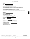
*WARNING :If the IGC mustbe replaced,be sureto groundyourself todissipateany electricalchargethat my be presentbeforehandlingnew control
board.Th e IGC issensitive tostatic electricity and my be damaged if the necessaryprecautionsare not taken.
IMPORTANT: Refer to Table 12---Troubleshooting Guide---Heating for additional troubleshooting analysis.
LEGEND
IGC—Integrated Gas Unit Controller
LED—Light ---EmittingDiode
48EZ --A