


13
Control Voltage Connections
Do not use any type of power--stealing thermostat. Unit control
problems may result.
Use no. 18 American Wire Gage (AWG) color--coded, insulated
(35_C minimum) wires to make the control voltage connections
between the thermostat and the unit. If the thermostat is located
more than 100 ft (30.5 m) from the unit (as measured along the
control voltage wires), use no. 16 AWG color--coded, insulated
(35_C minimum) wires.
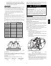
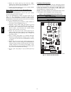
Locate the seven (eight on 3--phase) low voltage thermostat leads
in 24 volt splice box. See Fig. 9 for connection diagram. Run the
low--voltage leads from the thermostat, through the control wiring
inlet hole grommet (Fig. 2 and 3), and into the low--voltage splice
box. Provide a drip loop before running wires through panel.
Secure and strain relief all wires so that they do not interfere with
operation of unit. A gray wire is standard on 3 -- phase unit for
connection to an economizer.
Balance Point Setting--Thermidistat or Hybrid
Thermostat
BALANCE POINT TEMPERATURE--The “balance point”
temperature is a setting which affects the operation of the heating
mode. This is a field-- selected input temperature (range 5 to 55_F)
(--15to12_C) where the Thermidistat or dual fuel thermostat will
monitor outdoor air temperature and decide whether to enable or
disable the heat pump. If the outdoor temperature is above the
“balance point”, the heat pump will ener gize first to try to satisfy
the indoor temperature demand. If the heat pump does not make a
sufficient improvement within a reasonable time period (i.e. 15
minutes), then the gas furnace will come on to satisfy the indoor
temperature demand. If the outdoor temperature is below the
“balance point”, the heat pump will not be allowed to operate (i.e.
locked out), and the gas furnace will be used to satisfy the indoor
temperature. There are three separate concepts which are related to
selecting the final “balance point” temperature. Read each of the
following carefully to determine the best “balance point” in a
hybrid installation:
1. Capacity Balance Temperature: This is a point where the
heat pump cannot provide sufficient capacity to keep up
with the indoor temperature demand because of declining
outdoor temperature. At or below this point, the furnace is
needed to maintain proper indoor temperature.
2. Economic Balance Temperature: Above this point, the heat
pump is the most cost efficient to operate, and below this
point the furnace is the most cost efficient to operate. This
can be somewhat complicated to determine and it involves
knowing the cost of gas and electricity, as well as the
efficiency of the furnace and heat pump. For the most
economical operation, the heat pump should operate above
this tem perature (assuming it has sufficient capacity) and the
furnace should operate below this temperature.
3. Comfort Balance Temperature: When the heat pump is
operating below this point, the indoor supply air feels
uncomfortable (i.e. too cool). This is purely subjective and
will depend on the homeowner’s idea of comfort. Below
this temperature the gas furnace should operate in order to
satisfy the desire for indoor comfort.
Transformer Protection
The transformer is of the energy--limiting type. It is set to withstand
a 30-- sec. overload or shorted secondary condition. If an overload
or short is present, correct overload condition and check for blown
fuse on gas control board or Interface Fan Board. Replace fuse as
required with correct size and r ating.
PRE--START--UP
FIRE,EXPLOSION,ELECTRICALSHOCKHAZARD
Failureto followthiswarning could resultin personalinjury,
death or property damage.
1. Follow recognized safety practices and wear protective
goggles when checking or servicing refrigerant system.
2. Do not operate compressor or provide any electric power
to unit unless compressor terminal cover is in place and
secured.
3. Do not remove compressor terminal cover until all
electrical sources are disconnected and tagged.
4. Relieve and recover all refrigerant from system before
touching or disturbing anything inside terminal box if
refrigerant leak is suspected around compressor
terminals.
5. Never attempt to repair soldered connection while
refrigerant system is under pressure.
6. Do not use torch to remove any component. System
contains oil and refrigerant under pressure.
To remove a component, wear protective goggles and
proceed as follows:
a. Shut offelectrical power to unitand installlockout
tag.
b. Relieve and reclaim all refrigerant from system
using both high -- and low--pressure ports.
c. Cut component connecting tubing with tubing
cutter and remove component from unit.
d. Carefully unsweat remaining tubing stubs when
necessary. Oil can ignite when exposed to torch
flame.
!
WARNING
Proceed as follows to inspect and prepare the unit for initial
start--up:
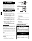
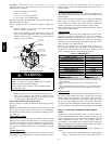
1. Remove access panels (see Fig. 18).
2. Read and follow instructions on all WARNING,
CAUTION, and INFORMATION labels attached to, o r
shipped with, unit.
3. Make the following inspections:
a. Inspect for shipping and handling damages such as
broken lines, loose parts, disconnected wires, etc.
b. Inspect for oil at all refrigerant tubing connections and
on unit base. Detecting oil generally indicates a
refrigerant leak.
c. Leak test all refrigerant tubing connections using
electronic leak detector, halide t orch, or liquid--soap
solution. If a refrigerant leak is detected, see the Check
for Refrigerant Leaks s ection.
d. Inspect all field-- and factory--wiring connections. Be
sure that connections are completed and tight.
e. Ensure wires do not touch refrigerant tubing or sharp
sheet metal e dges.
f. Inspect coil fins. If damaged during shipping and
handling, carefully straighten fins with a fin comb.
FIRE, EXPLOSION HAZARD
Failureto followthiswarning could resultin personalinjury,
death or property damage.
Donotpurgegassupplyintothecombustionchamber.Donot
use a match or other open flame to check for gas leaks. Use a
commercially available s oap s olution made specifically for
the detection of leaks to check all c onnections.
!
WARNING
48EZ --A