


18
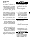
2. Remove the current speed tap wire from the “LOW”
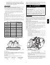
terminal on the interface fan board (IFB) (See Fig. 13) and
place vinyl cap over the connector on the wire.
3. Connect the desired speed tap wire to the “LOW” terminal
on the interface fan board (IFB).
Two Cooling Fan Speeds Set-up (Dehumidification
feature
used)
IMPORTANT: Dehumidification control must open control
circuit on humidity rise above set point.
Use of the dehumidification cooling fan speed requires use of
either a 24 VAC dehumidistat or a thermostat which includes
control of a 24 VAC dehumidistat connection. In either case, the
dehumidification control must open the control circuit on humidity
rise above the dehumidification set point.
1. Remove fan speed tap wire from the “LOW” terminal on
the interface fan board (IFB) (See Fig. 13).
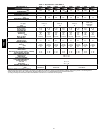
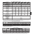
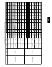
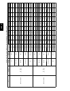
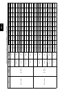
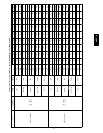
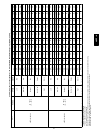
2. Determine correct normal cooling fan speed for unit and
application. Add the wet coil pressure drop in Table 9 to
the system static to determine the correct cooling airflow
speed in Ta ble 7 that will deliver the nominal cooling
airflow as listed in Table 1 for each size.
3. Remove the vinyl cap off of the desired speed tap wire
(Refer to Table 6 for color coding) for the normal cooling
fan s peed and place desired speed tap wire on “ HIGH” on
the interface board.
4. Refer to airflow tables (Table 7) to determine allowable
speeds for the dehumidification cooling fan speed. In Table
7, speeds that are not allowed for dehumidification cooling
are shaded.
5. Remove the vinyl cap off of the desired speed tap wire
(Refer to Table 6 for color coding) for the dehumidification
cooling fan speed and place desired speed tap wire on the
“LOW” connection on the interface board (IFB). Verify
that static pressure is in the acceptable range for the speed
tap to be used for dehumidification c ooling.
6. Use any spare vinyl plugs to cap any unused speed tap
wires.
Continuous Fan Operation
When the DEHUM feature is not used, the continuous fan speed
will be the same as cooling f an speed. When the DEHUM feature
is used, the continuous fan will operate on IFB “LOW” speed
when the DH c ontrol lead is not energized, or IFB “HIGH” speed
when the DH lead is energized (see Fig. 13).
NOTE: For heat pump operation, the recommended airflow is 350
to 450 CFM for each 12,000 Btuh of rated cooling capacity .
Table 6 – Color Coding for Indoor Fan Motor Leads
Black =High Speed
Orange =Med---High Speed
Red=MedSpeed
Pink = Med---Low Speed
Blue = Low Speed
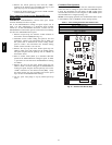
COMLOWHIGH
GAS
HEAT
Q1R1LC8RL3
Q3
DCR QCR
QC1
G1
G2
A7
D4D6C2OILL
R9 AB A15
C4
C9
C0
R4 RL4
C7
R2
R3 R5 R6
QCB
Y
YRUC24VAC
JW1
P2
P1
W2
Y2/ Y1/
YDH
GCR
SSTZ-8
P3
SDL
24VAC/R
CDM/C
F1
QC6 QC7 QC4 QC3
K2 K1
D2
RI0
RI2
JM6
RI DL
JM5
U1
C3
D3D5
JW3
JW2
JW4
JW7
3 AMP
C
A09058
Fig. 13 -- Interface Fan Board (IFB)
48EZ --A