


12
Step 10 — Install Electrical Connections
ELECTRICAL SHOCK HAZARD
Failure to follow this warning could result in personal injury
or death.
The unit cabinet must have an uninterrupted, unbroken
electrical ground. This ground may consist of an electrical
wire connected to the unit ground screw in the control
compartment,orconduitapprovedforelectricalgroundwhen
installed in accordance with NEC, NFPA 70 National Fire
Protection Association (latest edition) (in Canada, Canadian
Electrical Code CSA C22.1) and local electrical codes.
!
WARNING
UNIT COMPONENT DAMAGE HAZARD
Failureto followthiscaution may result in damage to theunit
being installed.
1. Ma ke all electrical connections in accordance with NEC
NFPA 70 (latest edition) and local electrical codes
governing such wiring. In Canada, all electrical
connections must be in accordance with CSA s tandard
C22.1 Canadian Electrical Code Part 1 and applicable
local codes. Refer to unit wiring diagram.
2. Use only copper conductor for connections between
field-- supplied electrical disconnect switch and unit. DO
NOT USE ALUMINUM WIRE.
3. Be sure that high -- voltage power to unit is within
operating voltage range indicated on unit rating plate. On
3--phase units, ensure phases are balanced within 2
percent. Consult local power company for correction of
improper voltage and/or phase imbalance.
4. Insulate low-- voltage wires for highest voltage contained
within conduit when low--voltage control wires are in
same conduit as high--voltage wires.
5. Do not damage internal components when drilling
through any panel to mount electrical hardware, conduit,
etc.
!
CAUTION
High--Voltage Connections
When routing power leads into unit, use only copper wire between
disconnect and unit. The high voltage leads should be in a conduit
until they enter the duct panel; conduit termination at the duct
panel must be watertight.
The unit must have a separate electrical service with a
field-- supplied, waterproof disconnect switch mounted at, or within
sight from, the unit. Refer to the unit rating plate, NEC and local
codes for maximum fuse/circuit breaker size and minimum circuit
amps (ampacity) for wire sizing.
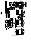
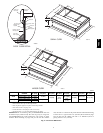
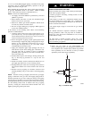
The field--supplied disconnect switch box may be mounted on the
unit over the high-- voltage inlet hole when the standard power and
low--voltage entry points a re used (See Fig. 2 and 3 for acceptable
location).
NOTE: Field supplied disconnect switch box should be
positioned so that it does not cover up any of the unit gas
combustion supply air louvers.
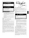
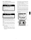
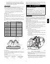
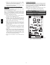
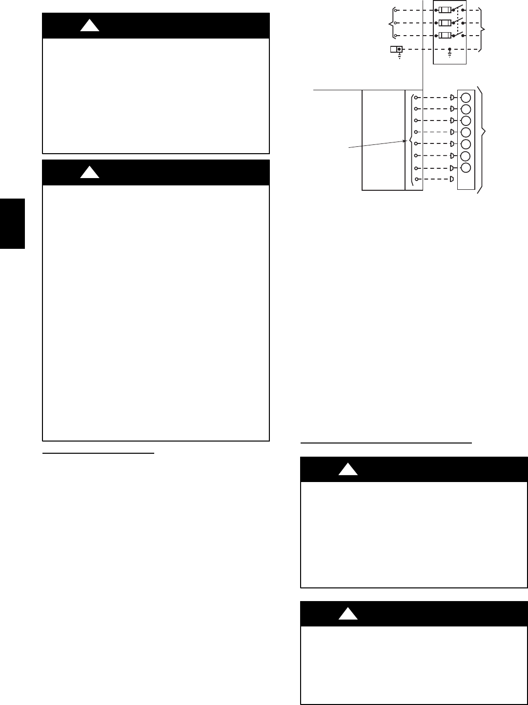
See unit wiring l abel (Fig. 14 and 15) and Fig. 9 for reference
when making high voltage connections. Proceed as follows to
complete the high--voltage connections to the unit.
Single phase units:
1. Run the high -- voltage (L1, L2) and ground lead into the
control box.
2. Connect ground lead to chassis ground connection.
POWER
SUPPLY
FIELD-SUPPLIED
FUSED DISCONNECT
HIGHVOLTAGE
POWER LEADS
(SEE UNITWIRING
LABEL)
EQUIP GR
CONTROL BOX
SPLICE BOX
LOW-VOLTAGE
POWER LEADS
(SEE UNIT
WIRING LABEL)
W
Y
G
R
C
WHT(W1)
YEL(Y)
GRN(G)
RED(R)
BRN(C)
THERMOSTAT
(TYPICAL)
O
ORN(O)
GRA (Y2)
BLU (DH)
DH
3-Phase
Only
A09067
Fig. 9 -- High and Control --Voltage Connections
3. Locate the black and yellow wires connected to the line side
of the contactor.
4. Connect field L1 to black wire on connection 11 of the
compressor contactor.
5.ConnectfieldwireL2toyellowwireonconnection23of
the compressor contactor.
Three--phase units:
1. Run the high-- voltage (L1, L2, L3) and ground lead into the
control box.
2. Connect ground lead to chassis ground connection.
3. Locate the black and yellow wires connected to the line side
of the contactor.
4. Connect field L1 to black wire on connection 11 of the
compressor contactor.
5.ConnectfieldwireL3toyellowwireonconnection13of
the compressor contactor.
6. Connect field wire L2 to blue wire from compressor.
Special Procedures for 208--V Operation
ELECTRICAL SHOCK HAZARD
Failure to follow this warning could result in personal injury
or death.
MakesurethepowersupplytotheunitisswitchedOFFbefore
makinganywiring changes.Tagthedisconnectswitch witha
suitable warning label. With disconnect switch open, move
black wirefromtransformer(3/16in.) terminalmarked 230to
terminal marked 200. This retaps transformer to primary
voltage of 208 vac.
!
WARNING
ELECTRICAL SHOCK AND EXPLOSION HAZARD
Failure to follow this warning could result in personal injury
or death.
Beforemakinganywiringchanges, makesurethegassupply
is switched off first. Then switch off the power supply to the
unit and install lockout tag.
!
WARNING
48EZ --A