


15
integrated gas unit controller (IGC) has the capability to
automatically reduce the evaporator “ON” delay and in-
crease t he evaporator “OFF” delay in the event of high duct
static and/or partially--clogged filter.
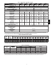
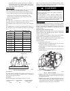
Check Gas Input
Check gas input and manifold pressure after unit start--up (See
Table 3). If adjustment is required proceed as follows:
S The rated gas inputs shown in Table 3 arefor altitudes from s ea
level to 2000 ft (610 m) above sea level. These inputs arebased
on natural gas with a heating value of1025 Btu/ft
3
at 0.60
specific gravity, or propane gas with a heating value of 2500
Btu/ft
3
at 1.5 specific gravity .
IN THE U.S.A.:
The input rating for altitudes above 2,000 ft (610 m) must be
reduced by 4% for each 1,000 ft (305 m) above sea level.
For installations below 2,000 ft (610 m), refer to the unit rating
plate.
For installations above 2,000 ft (610 m) multiply the input by on
the rating plate by the derate multiplier i n Table 4 for correct input
rate.
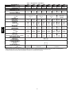
Table 4 – Altitude Derate Multiplier for U.S.A.*
ALTITUDEFT(M) PERCENT OF DERA TE
DERATEMULTIPLIER
FACTOR{
0---2000
(0---610)
0 1.00
2001---3000*
(610---914)
8---12 0.90
3001---4000
(315---1219)
12---16 0.86
4001---5000
(1220---1524)
16---20 0.82
5001---6000
(1524---1829)
20---24 0.78
6001---7000
(1829---2134)
24---28 0.74
7001---8000
(2134---2438)
28---32 0.70
8001---9000
(2439---2743)
32---36 0.66
9001---10,000
(2744---3048)
36---40 0.62
*In Canadasee Canadian Altitude Adjustment.
{Derate multiplier factors are based on m idpoint altitude for altitude range.
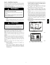
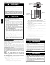
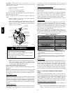
MANIFOLD
BURNER
BURNER FLAME
C99021
Fig. 10 -- Monoport Burner
IN CANADA:
The input rating for altitudes from 2,000 to 4,500 ft (610 m to
1372 m) above sea level must be derated 10% by an authorized
Gas Conversion Station or Dealer.
EXAMPLE:
90,000 Btu/hr Input Furnace Installed at 4300 ft (1311 m).
FurnaceInput Rate at
Sea Level
XDerateMultiplier
Factor
= Furnace Input Rate at
Installation Altitude
90,000 X 0.90 = 81,000
When the gas supply being used has a different heating value or
specific gravity, refer to national and local codes, or contact your
distributor to determine the required orifice size.
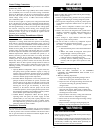
UNIT DAMAGE HAZARD
Failure to follow this caution may result in reduced unit
and/or component life.
Do Not redrill an orifice. Improper drilling ( burrs,
out--of--round holes, etc.) can cause excessive burner noise
and misdirection of burner flame. If orifice hole appears
damaged or it is s uspected to have been redrilled, check
orifice hole with a numbered drill bit of correct size.
!
CAUTION
Adjust Gas Input
The gas input to the unit is determined by measuring the gas flow
at the meter or by measuring the manifold pressure. Measuring the
gas flow at the meter is recommended for natural gas units. The
manifold pressure must be measured to determine the input of
propane gas units.
Measure Gas Flow (Natural Gas Units)
Minor adjustment to the gas flow can be made by changing the
manifold pressure. The manifold pressure must be maintained
between 3.2 and 3.8 IN. W.C.
If larger adjustments are required, change main burner orifices
following the recommendations of national and local codes.
NOTE: All other appliances that use the same meter must be
turned off when gas flow is measured at the meter.
Proceed as follows:
1. Turn off gas supply to unit.
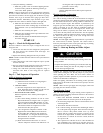
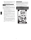
2. Remove pipe plug on manifold (See Fig. 11) and connect
manometer. Turn on gas supply to unit.
3. Record number of seconds for gas meter test dial to make
one revolution.
4. Divide number of seconds in Step 3 into 3600 (number of
seconds in one hr).
Pipe Plug
Manifold
A07679
Fig. 11 -- Burner Assembly
5. Multiply result of Step 4 by the number of cubic feet (cu ft)
shown for one revolution of test dial to obtain cubic feet (cu
ft) of gas flow per hour.
6. Multiply result of Step 5 by Btu heating value of gas to
obtain total measured input in Btuh. Compare this value
with heating input shown in Table 3 (Consult the local gas
supplier if the heating value of gas is not known).
48EZ --A