


11
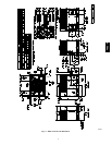
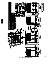
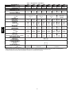
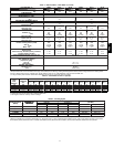
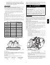
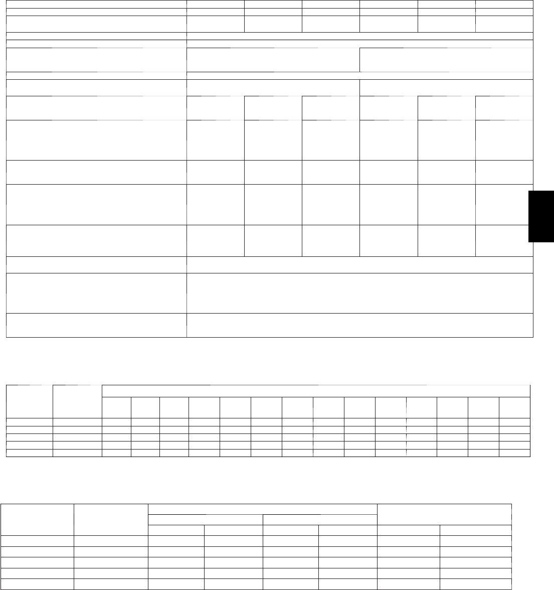
Table 1 -- Physical Data -- Unit 48EZ--A (Cont’d)
UNIT SIZE 48EZ ---A 48090 48115 48130 60090 60115 60130
NOMINAL CAPACITY ---ton 4 4 4 5 5 5
OPERATING WEIGHT---lb
(kg)
482
219
482
219
482
219
507
230
507
230
507
230
COMPRESSORS Scroll
Quantity 1
REFRIGERANT (R---410A)
Quantity ---lb
(kg )
9.6
4.4
12.3
5.6
REFRIGERANT METERING DEVICE TXV
OUTDOOR ORIFICE---in. (qty)
(mm)
0.046 (2)
1.2
0.052 (2)
1.3
OUTDOOR COIL
Rows...Fins---in.
Face Area --- sq ft
2...21
13.6
2...21
13.6
2...21
13.6
2...21
17.5
2...21
17.5
2...21
17.5
OUTDOOR FAN
Nominal Cfm
Diameter---in.
(mm)
Motor Hp --- Rpm
3100
26
660
1/5 (810)
3100
26
660
1/5 (810)
3100
26
660
1/5 (810)
3500
26
660
1/5 (810)
3500
26
660
1/5 (810)
3500
26
660
1/5 (810)
INDOOR COIL
Rows...Fins---in.
Face Area --- sq ft
3...17
4.7
3...17
4.7
3...17
4.7
3...17
5.7
3...17
5.7
3...17
5.7
INDOOR BLOWER
Nominal Cooling Airflow---(CFM)
Size --- in.
(mm)
Motor --- hp
1600
11x10
279x254
1.0
1600
11x10
279x254
1.0
1600
11x10
279x254
1.0
1850
11x10
279x254
1.0
1850
11x10
279x254
1.0
1850
11x10
279x254
1.0
FURNACE SECTION*
Burner Orifice
Natural Gas Qty ...Drill Size (Factory Installed)
Propane GasQty...Drill Size
3...38
3...53
3...33
3...51
3...31
3...49
3...38
3...53
3...33
3...51
3...31
3...49
HIGH---PRESSURE SWITCH (psig) Cut---out
Reset (Auto)
650 +/---15
420 +/---25
LOSS--- OF --- CHARGE /
LOW---PRESSURE SWITCH
(Liquid Line) (psig)
Cut --- out
Reset (auto)
20 +/ ---5
45 +/---10
RETURN ---AIR FILTERS†
Throwaway (in.)
(mm)
24x36x1
(610x914x25)
*Based ona ltitude of 0to 2000 ft( 0---610 m).
{Requiredfiltersizesshownare based on the largerof theAHRI(Air Conditioning,Heatingand Refrigeration Institute)ratedcooling airflowor theheating airflow
velocity of 300 ft/minute for high---capacity type. Air filter pressure drop for non---standard filters must not exceed 0.08 IN. W.C.
} If usingaccessory filter rack refer to filter rack installation instructionsfor correctfiltersize andquantity.
Table 2 – Maximum Gas Flow Capacity*
NOMINAL
IRON
PIPE,
SIZE (IN.)
INTERNAL
DIAMETER
(IN.)
LENGTH OF PIPE, FT† (m)
10
(3.1)
20
(6.1)
30
(9.1)
40
(12.2)
50
(15.2)
60
(18.3)
70
(21.3)
80
(24.4)
90
(27.4)
100
(30.5)
125
(38.1)
150
(46.0)
175
(53.3)
200
(61.0)
1/2 .622 175 120 97 82 73 66 61 57 53 50 44 40 — —
3/4 .824 360 250 200 170 151 138 125 118 110 103 93 84 77 72
1 1.049 680 465 375 320 285 260 240 220 205 195 175 160 145 135
1 --- 1/4 1.380 1400 950 770 600 580 530 490 460 430 400 360 325 300 280
1 --- 1/2 1.610 2100 1460 1180 990 900 810 750 690 650 620 550 500 460 430
* Capacity of pipe in cu ft of gas per hr for gas pressure of 0.5 psig or less. Pressure drop of 0.5---IN. W.C. (based on a 0.60 specific gravity gas). Refer toTable2
and National Fire Protection Association NFPA 54/ANSIZ223.1.
† Thislengthincludesan ordinary numberof fittings.
Table 3 – Heating Inputs
HEATING INPUT
(BTUH)
NUMBER
OF
GAS SUPPLY PRESSURE ( IN. W.C.)
MANIFOLD PRESSURE
NUMBER
OF
ORIFICES
Natural{ Propane*{
MANIFOLD
PRES
SURE
(IN. W.C.)
ORIFICES
Min Max Min Max Natural{ Propane*†
40,000 2 4.0 13.0 11.0 13.0 3.2∼3.8 10.0∼11.0
60,000 2 4.0 13.0 11.0 13.0 3.2∼3.8 10.0∼11.0
90,000 3 4.0 13.0 11.0 13.0 3.2∼3.8 10.0∼11.0
115,000 3 4.0 13.0 11.0 13.0 3.2∼3.8 10.0∼11.0
130,000 3 4.0 13.0 11.0 13.0 3.2∼3.8 10.0∼11.0
*When a unit is converted to propane, different size orifices must be used. See separate, natural---to---propane conversion kit instructions.
{Basedon al titudes from sea level to 2000 ft(610 m) above sea level. In U.S.A. for altitudes above 2000 ft(610 m), reduce input rating 4 percent for each addi-
tional 1000 ft(305 m) above sea level. In Canada, from 2000 ft( 610 m) above sea level to 4500ft (1372 m) above sea level, derate the unit 10 percent.
48EZ --A