18
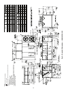
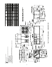
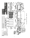
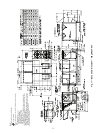
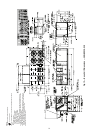
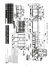
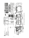
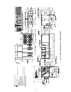
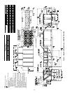
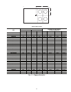
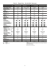
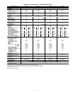
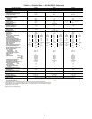
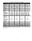
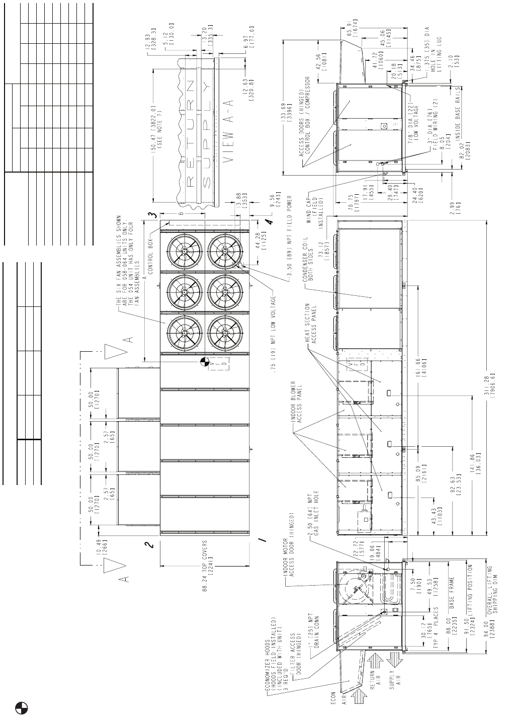
Fig. 16 — Base Unit Dimensions — 48EW,EY054-068
NOTES:
1. Weights include economizer (standard).
2. Center of Gravity.
3. Do not locate adjacent units with flue discharge
facing economizer inlet.
Min Clearances to be:
Adjacent Units: 15′-0″ [4572].
Top of Units: No Overhang.
Condenser Coil: 4′-0″ [1219].
Economizer Side: 6′-0″ [1829].
Heat Side: 4′-0″ [1219].
Filter Access Side: 15′-0″ [4572]. (For
removal of evaporator coil.)
4. For smaller service and operational clearances
contact Carrier Application Engineering Depart-
ment.
5. Base unit weights include outdoor air hoods
and filters (indoor fan motor is not included).
Add indoor motor, FIOPs and accessories for
total operating weight.
6. VAV motor weights include indoor motor, VFD,
compressor electric unloaders, VFD transducer
and associated wiring.
7. For side-supply/return applications, a single
return and supply ductwork connection is rec-
ommended for covering all three return and all
three supply openings. The entire area around
the duct openings is available for a 1.5″ duct
flange attachment
8. Dimensions in are in inches [mm].
BASE UNIT WEIGHTS
(See Note 6) lbs (kg)
054 058 064 068
48EWD/EYD 6845 (3105) 7095 (3218) 7345 (3332) 7520 (3411)
48EWE 7085 (3214) 7335 (3327) 7585 (3441) 7760 (3520)
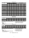
UNIT SIZE
CENTER OF GRAVITY
% OF TOTAL WEIGHT
AT EACH CORNER
Inches Millimeters
ABAB1234
48EWD/EYD054 130.9 46.9 3325 1192 22.4 19.6 27.0 30.9
48EWE054 133.8 47.4 3397 1204 23.1 19.8 26.3 30.7
48EWD/EYD058 132.1 47.5 3354 1207 22.9 19.5 26.5 31.1
48EWE058 139.5 49.6 3544 1260 25.3 19.6 24.1 31.1
48EWD/EYD064 125.3 45.2 3181 1149 20.7 19.6 29.1 30.7
48EWE064 132.2 47.2 3359 1199 22.8 19.7 26.7 30.8
48EWD/EYD068 127.7 46.6 3242 1184 21.7 19.3 27.7 31.2
48EWE068 134.7 48.6 3422 1235 23.9 19.4 25.4 31.3


