


9
38QRF Units
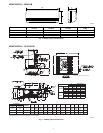
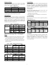
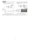
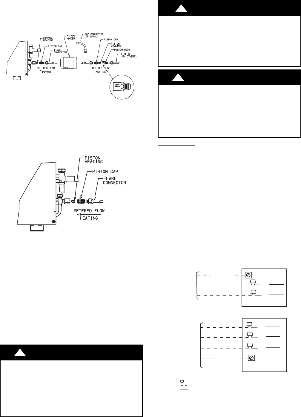
1. Assemble the connector tubes to the factory supplied filter
drier by brazing the factory supplied flare connectors to the
inlet and outlet for the filter drier (see Fig. 19)
A09507
Fig. 19 -- 38QRF018--036 Connector Tube Assembly
2. Perform step 2 and 3 from the 38HDF section.
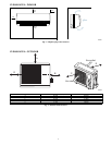
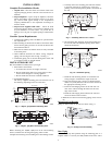
3. Remove the plastic cap from the liquid and suction service
valve on the 38QRF unit and assemble the heating piston
and piston cap supplied with the outdoor unit as shown in
Fig. 20.
A07407
Fig. 20 -- AccuRater (bypass type)
Metering Device Components
NOTE: The Teflon seal on the piston should point towards the
liquid service valve. The size of the factory supplied piston might
have to be adjusted for long line applications (over 80 ft / 24.4 m).
Refer to the Duct Free Long Line Application Guide for additional
information.
4. Attach the flare end of the filter drier assembly to the piston
cap (see Fig. 20).
5. Connect the field supplied line set to the filter drier as-
semblyandtothesuctionvalve.
6. Insulate any exposed areas between filter drier and liquid
valve.
Complete Outdoor Power and Control Wiring
!
WARNING
ELECTRICAL SHOCK HAZARD
Failure to follow this warning could result in personal injury or
death.
The unit cabinet must have an uninterrupted or unbroken
ground to minimize personal injury if an electrical fault should
occur. The ground may consist of electrical wire or metal
conduit when installed in accordance with existing electrical
codes.
CAUTION
!
UNIT DAMAGE HAZARD
Failure to follow this caution may result in equipment damage
or improper operation.
Unit failure as a result of operation on improper line voltage or
excessive phase imbalance constitutes abuse and may cause
damage to electrical components. Such operation could void
any applicable Carrier warranty.
!
WARNING
ELECTRICAL SHOCK HAZARD
Failure to follow this warning could result in personal injury or
death.
Before performing service or maintenance, be sure indoor unit
main power switch is turned OFF and indoor blower has
stopped.
Lock out and tag switch with a suitable warning label.
Power Wiring
1. Mount outdoor power disconnect. The unit is factory wired
for the voltage shown on the unit nameplate. The fused dis-
connect switch must be provided within sight of the unit,
readily accessible, but out of reach of children. Provisions
for locking the disconnect switch on the OFF (open) posi-
tion is advisable. The disconnect switch must comply with
NEC and local codes. Protect the unit and wiring using only
the recommended fuse/circuit breaker size. See Table 10..
2. Run power wiring from main box to disconnect per NEC
and local codes.
3. Run power wiring from the disconnect switch to outdoor
unit. Use only minimum 60_C copper conductors between
the disconnect switch and the unit for field power connec-
tion.
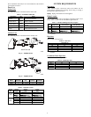
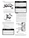
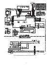
4. Route the field power wires through the conduit connection
opening in the unit side panel and connect in junction box
as shown in Fig 21. The unit and power wiring must be
grounded.
BLK
BLK
SINGLE-PHASE UNIT
GROUNDING LUG
SINGLE-PHASE
CONN TO
DISCONNECT
PER NEC
BLK
BLU
YEL
GROUNDING LUG
THREE-PHASE
CONN TO
DISCONNECT
PER NEC
THREE-PHASE UNIT
GROUND LEAD
GROUND LEAD
LEGEND
NEC -- National Electrical Code
-- Splice (field)
Field Wiring
Factory Wiring
A08251
Fig. 21 -- Line Power Connections
NOTE: Operating unit on improper line voltage constitutes abuse
and could affect Carrier warranty. Do not install unit in a system
where voltage may fluctuate above or below permissible limits.