


4
These installation instructions cover the installation of the matched
systems listed in table 2.
Parts List
Indoor Unit
The following items are included with the indoor unit:
Table 1 – Installation Materials
Description Qty Usage
Wall Mounting
Bracket
1 For Indoor Unit Installation
Screws, 4XL10 2
For Attaching The Remote Control
Holder To The Wall
Screws, 5XL25 5/ 14*
For Attaching The Mounting Bracket To
The Wall
Remote Control 1 For Controlling Unit
Remote Control
Holder
1 Holder For Remote Control
* 5 screws for unit sizes 18 and 24. 14 scr e ws for unit sizes 30 and 36.
Outdoor Unit
The following items are included with the outdoor unit:
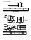
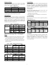
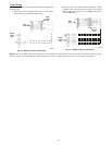
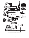
38HDF018-036
A09499
Fig. 5 -- 38HDF018--036
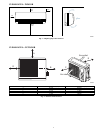
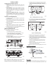
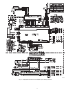
A09500
Fig. 6 -- 38QRF018--036
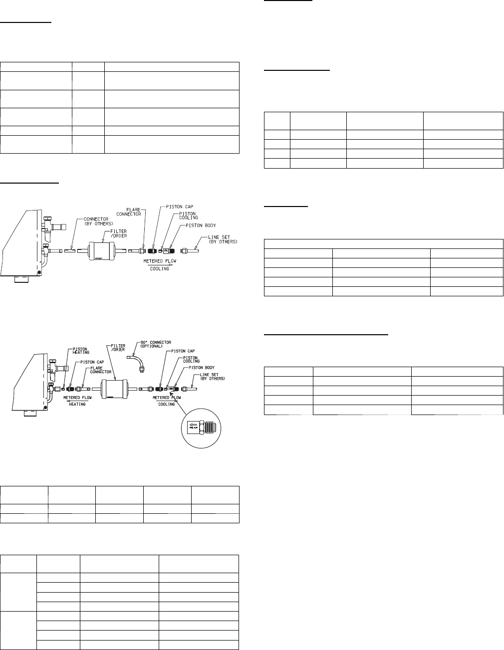
Model Filter Drier
Piston
Cap
Pistons*
Flare
Connector
38HDF n n n n
38QRF n n (qty 2) n n (qty 3)
* Multiple pistons. Quantity varies with size.
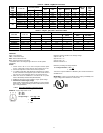
Table 2 – Matched Systems
System
Type
Nominal
Capacity
Outdoor
Unit
Indoor
Unit
Cooling
Only
018 38HDF018 --- --- --- 3 40QNC018024--- ------3
024 38HDF024 --- --- --- 3 40QNC018024--- ------3
030 38HDF030 --- --- --- 3 40QNC030 --- --- --- 3
036 38HDF036---------3/5/6 40QNC036 --- --- --- 3
Heat
Pump
018 38QRF018 --- --- --- 3 40QNQ018 --- --- --- 3
024 38QRF024 --- --- --- 3 40QNQ024 --- --- --- 3
030 38QRF030 --- --- --- 3 40QNQ030 --- --- --- 3
036 38QRF036------ ---3/5/6 40QNQ036 --- --- --- 3
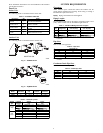
SYSTEM REQUIREMENTS
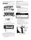
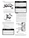
Clearances
Allow sufficient space around the indoor and outdoor unit for
proper airflow circulation and servicing. Refer to Fig. 3 and Fig. 4
for minimum required clearances.
Piping: Piping and insulation is field supplied.
Piping Lengths
The minimum length between the indoor and outdoor units is 10 ft
(3 m). Refer to table 3 for the maximum lengths allowed.
Table 3 – Maximum Refrigerant Line Lengths
Unit
Size
Max Line
Length ft(m)
Max Elevation (ID
over OD) ft(m)
Max Elevation (OD
over OD) ft(m)
18K 200 (61) 65 (19.8) 200 (61)
24K 200 (61) 65 (19.8) 200 (61)
30K 200 (61) 65 (19.8) 200 (61)
36K 200 (61) 65 (19.8) 200 (61)
Note:For lengths greater than 25 ft (7.6 m), refer to the Duct Free Long
Line Guide.
Pipe Sizes
Refer to table 4 for pipe sizes.
Table4–PipeSizes
Pipe Sizes (in)
Unit Size M ix Pha s e --- i n Vapor --- in
18K 3/8 5/8
24K 3/8 5/8
30K 3/8 3/4
36K 3/8 3/4
Note:Both lines need to be insulated using at least 1/2 inch closed foam
insulation.
Condensate Drain Pipe Sizes
Refertotable5fortherequiredsizes.
Table 5 – Drain Pipe Sizes
Unit Size Outside Diameter --- in Inside Diameter --- in
18K 5/8 7/16
24K 5/8 7/16
30K 3/4 5/9
36K 3/4 5/9
Note:Do not trap condensate pipe.