


16
Run Power Wiring for Indoor Unit
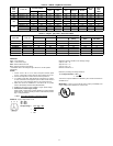
Be sure field wiring complies with local building codes and NEC,
and unit voltage is within limits shown in Table 11.
Contact local power company for correction of improper line
voltage.
!
WARNING
ELECTRICAL SHOCK HAZARD
Failure to follow this warning could result in personal injury
or death.
Before installing, modifying, or servicing system, main
electrical disconnect switch must be in the OFF position.
There may be more than 1 disconnect switch. Lock out and
tag switch with a suitable warning label.
CAUTION
!
UNIT DAMAGE HAZARD
Failure to follow this caution may result in equipment damage
or improper operation.
Unit failure as a result of operation on improper line voltage or
excessive phase imbalance constitutes abuse and may cause
damage to electrical components. Such operation could void
any applicable Carrier warranty.
NOTE: Use copper wire only between disconnect switch(es) and
unit.
NOTE: Install branch circuit disconnect of adequate size to handle
unit starting current per NEC. Locate disconnect within sight of,
and readily accessible from, unit, per section 440--14 of NEC.
Some codes allow indoor unit to share disconnect with outdoor
unit if disconnect can be locked; check local code before installing
in this manner.
The 40QNC/QNQ units require their own power supply.
1. Locate the indoor power supply.
2. Locate and install disconnect switch per NEC and local
codes.
3. Run power supply wiring to disconnect switch.
4. Run power wiring from disconnect switch to wall mount
area.
5. If any accessories are being installed, refer to the individual
accessory instructions for guidance on wire routing at this
time.
Install All Power, Interconnecting Wiring, Piping and
Drain Hose to Indoor Unit
.
1. Run control wiring from the outdoor unit through the access
hole in the wall and make sure you have enough wire to
reach the control box of the unit once hung on the mounting
plate.
2. It is a recommended that flare connections is located on the
outside of the wall where the indoor unit is to be mounted.
If an extension pipe is required to facilitate this location,
measure, fabricate and install the extension pipes to the in-
door unit before hanging the unit on the mounting bracket.
3. If piping connections are on the outside wall, pass the pipes
(refrigerant and drain) through the wall sleeve and then
hook the indoor unit body on top of the wall hanging brack-
et. Support the unit away from the bottom using a tool or a
piece of wood.
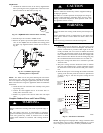
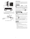
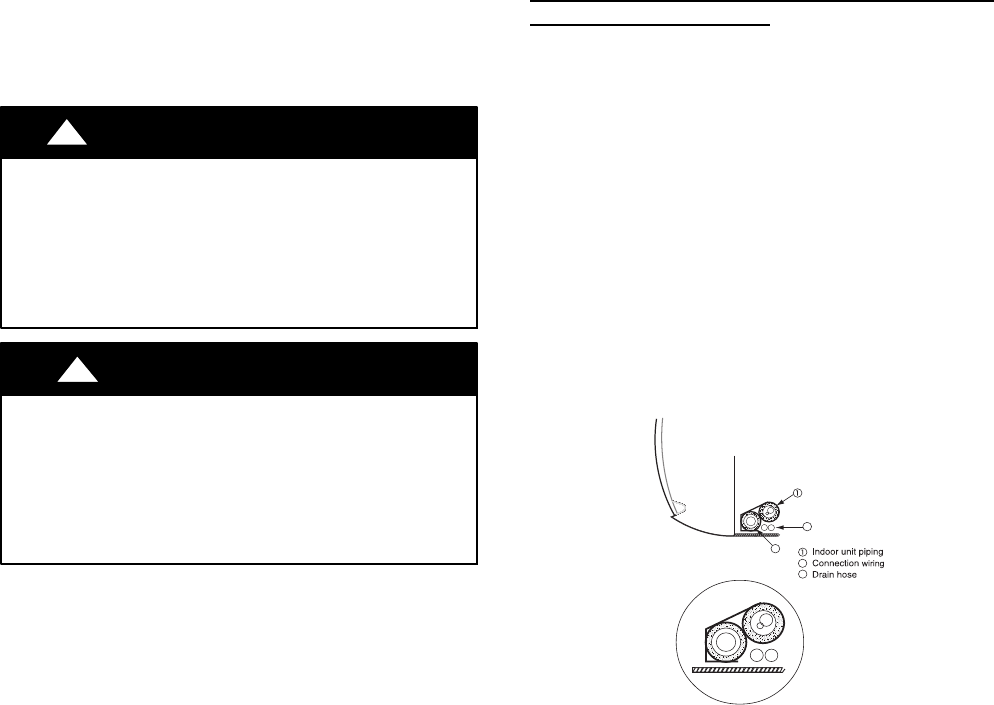
NOTE: Tie together the refrigerant piping, the drain hose, and the
electrical connection wires and ensure that the drain hose is at the
bottom as shown in Fig. 28.
2
3
2
3
A08364
Fig. 28 -- Location of Piping, Hose, and Wiring
4. If required make the flare connections.
5. Route the power and control wiring through the back side
of the unit and to the control box area. If the wired remote
or zone manger accessory are to be used, perform any modi-
fications required at this time. Refer to the Accessory install-
ation instructions).
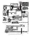
6. Remove the control box cover and finish all indoor unit
wiring connections as shown on the wiring diagram or in
the accessory installation instructions. Replace the control
box cover.
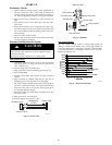
7. Fix the bottom part of the unit to the wall mounting bracket
and push it carefully until the two bracket hooks fit into the
marked places at the base of the unit until it snaps into
place. See Fig. 29.