


6
INSTALLATION
Complete Pre--installation Checks
1. Unpack Unit -- Store the indoor and outdoor units in the
original packaging until it is moved to the final site for in-
stallation.
2. Inspect Shipment -- Upon receipt of shipment, check the
indoor and outdoor units for damage. If there is any dam-
age, forward claim papers directly to the transportation
company. Manufacturer is not responsible for damage in-
curred in transit.
3. Inspect Parts Supplied With Units – Check all items
against parts list (see Table 1). If any items are missing, noti-
fy your distributor or Carrier office. To prevent loss or
damage, leave all parts in original packages until installa-
tion.
Consider System Requirements
1. Consult local building codes and NEC for special installa-
tion requirements.
2. When deciding the location of the indoor and outdoor units,
ensure that the piping run does not exceed the allowed dis-
tances listed in Table 3.
3. Make sure the indoor and outdoor units are easily accessible
to electrical power.
4. Allow sufficient clearances for airflow, wiring, refrigerant
piping, and servicing the unit. See Fig. 3 and Fig. 4.
5. Condensate piping can be directed through the inside wall
to an approved drain or straight outside.
INSTALL INDOOR UNIT
Plan the installation carefully before you begin.
1. Select indoor unit location.
a. A location that can bear the weight of the unit.
b. Do not install indoor units near a direct source of heat
such as direct sunlight or a heating appliance.
c. Do not install units too close to humid conditions.
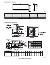
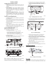
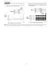
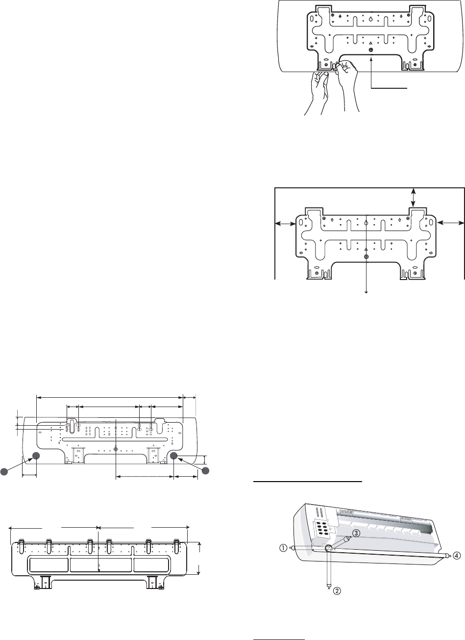
2. Install Mounting Plate
The factory supplied mounting plate will look like one of
the following depending on the size of the unit.
2.1"
(53.3)
14.9" (378.5)
3.5"
(88.9)
2.8"
(71.1)
2.8"
(71.1)
B
5.1”
(129.5)
13.8" (130.5)
A
2"
(50.8)
7.7" (195.6)
35.4” (899.2)
2.1"
(53.3)
1"
(25.4)
Note: Numbers in ( ) = mm
A09046
Fig. 7 -- 40QNC, QNQ018,024 Mounting Plate
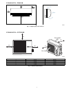
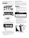
27.1”
(688.3)
27.2”
(690.9)
8.4” (213)
Measurements in ( ) = mm
A09047
Fig. 8 -- 40QNC, QNQ030, 036 Mounting Plate
Before mounting the 40QNC, QNQ unit on the wall mounting
bracket, consider how the refrigerant piping will be routed.
Complete the following when installing the wall mounting bracket:
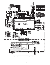
a. Carefully remove the mounting plate which is attached
to the back of the unit by removing any screws and
pushing at the indicated pressure points at the bottom of
the unit.
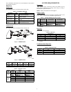
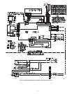
Remove Screw
A09048
Fig. 9 -- Mounting Plate Screw Location
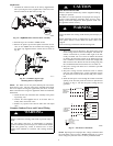
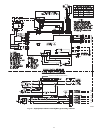
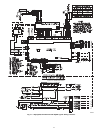
b. The mounting plate should be located horizontally and
level on the wall. All minimum spacing shown below
should be maintained.
12”
(304.8)
min.
Plumb line
5” (127) min.
18”
(457.2)
min.
Note: Numbers in ( ) = mm
A09049
Fig. 10 -- Minimum Spacing
c. Install the wall mounting bracket in a location that is
strong enough to withstand the weight of the unit.
d. If the wall is block, brick, concrete or similar material,
drill 0.2 in (5 mm) diameter holes and insert anchors for
the appropriate mounting screws.
e. Fasten the wall hanging bracket to the wall with 4 or
more screw anchors through the holes near the outer
edge of the bracket.
f. Install the wall hanging bracket flush to the wall, and
ensure the bracket does not move.
3. Drill hole in wall for interconnecting piping, drain, and wir-
ing
Refrigerant Line Routing
Piping for indoor units can be routed as shown in Fig. 11.
A08358A
Fig. 11 -- Refrigerant Line Routing
Rear Piping
Determine the pipe hole position using the mounting plate as a
template. Drill a 2--1/2 inch (63.5 mm) diameter hole in the wall at