


20
START--UP
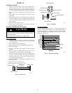
Preliminary Checks
1. Check condensate drainage system; on the opposite side of
the drain connection, insert a water bottle up into the fan
coil unit and fill the drain pan. Water must flow steadily; if
not, check the pipe slope or inspect for any pipe restrictions.
2. Make sure all wiring connections are correct and they are
tight.
3. Field electrical power source must agree with unit name
plate rating.
4. Check that all barriers, covers, and panels are in place. En-
sure that the filters and return--air grilles on the indoor unit
have been installed and that the discharge louvers are posi-
tioned correctly.
5. All service valves must be closed.
6. On units with crankcase heaters, ensure belly--band heaters
are tight around the compressor.
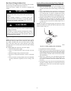
Evacuate and Dehydrate the System
CAUTION
!
UNIT DAMAGE HAZARD
Failure to follow this caution may result in equipment damage
or improper operation.
Never use the system compressor as a vacuum pump.
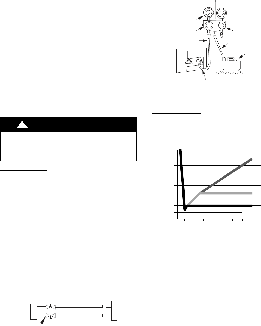
Using Vacuum
Pump
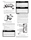
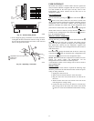
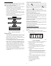
1. Completely tighten flare nuts A, B, C, D, connect manifold
gage charge hose to a charge port of the low side service
valve. (See Fig. 34.)
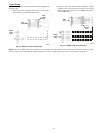
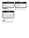
2. Connect charge hose to vacuum pump.
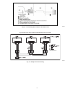
3. Fully open the low side of manifold gage. (See Fig. 35)
4. Start vacuum pump
5. Evacuate using either deep vacuum or triple evacuation
method.
6. After evacuation is complete, fully close the low side of
manifold gage and stop operation of vacuum pump.
7. The factory charge contained in the outdoor unit is good for
up to 25 ft. (8 m) of line length. For refrigerant lines longer
than 25 ft (8 m), add 0.3 oz. per foot of extra piping up to
the maximum allowable length.
8. Disconnect charge hose from charge connection of the low
side service valve.
9. Fully open service valves B and A.
10. Securely tighten caps of service valves.
Outdoor Unit
Indoor Uni
t
Refrigerant
Service Valve
Low Side
High Side
A
B
C
D
A07360
Fig. 34 -- Service Valve
Manifold Gage
500 microns
Low side valve
High side valve
Charge hose
Charge hose
Vacuum pump
Low side valve
A07361
Fig. 35 -- Manifold
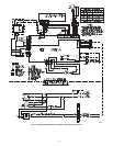
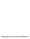
Deep Vacuum
Method
The deep vacuum method requires a vacuum pump capable of
pulling a vacuum of 500 microns and a vacuum gage capable of
accurately measuring this vacuum depth. The deep vacuum method
is the most positive way of assuring a system is free of air and
liquid water. (See Fig. 36)
500
MINUTES
01234567
1000
1500
LEAK IN
SYSTEM
VACUUM TIGHT
TOO WET
TIGHT
DRY SYSTEM
2000
MICRONS
2500
3000
3500
4000
4500
5000
A95424
Fig. 36 -- Deep Vacuum Graph