


8
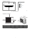
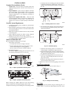
Mounting Unit on Wall
The units can also be mounted on the wall using the accessory
mounting kit.
Complete Outdoor Refrigerant Piping Connec-
tions
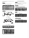
Follow the following general guidelines:
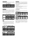
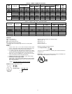
1. Use refrigerant grade field – supplied tubing.
Refer to Table 4 for the correct line sizes.
2. Do not use less than 10 ft (93.05 m) of interconnecting
tubing.
CAUTION
!
UNIT DAMAGE HAZARD
Failure to follow this caution may result in equipment
damage or improper operation.
If any section of pipe is buried, there must be a 6 in. (152.4
mm) vertical rise to the valve connections on the outdoor
unit. If more than the recommended length is buried,
refrigerant may migrate to cooler, buried section during
extended periods of system shutdown. This causes
refrigerant slugging and could possibly damage the
compressor at start--up.
When more than 80 ft (24.4 m) of interconnecting tubing is used,
consult the Duct--Free Split System Long Line Application Guide
for required accessories.
3. Insulate both lines. A minimum of 1/2 inch foam pipe insu-
lation is recommended.
4. Run the refrigerant tubes as directly as possible and avoid
unnecessary turns and bends.
5. Suspend refrigerant tubes to avoid damage to insulation or
tubes so they do not transmit vibration to the structure.
6. When passing refrigerant tubes through the wall, seal the
opening so rain and insects do not enter the structure. Leave
some slack in refrigerant tubes between structure and out-
door unit to absorb vibration.
NOTE: A fusible plug is located in unit suction line; do not cap
this plug. If local codes require additional safety devices, install as
directed.
Connection at Outdoor Unit
CAUTION
!
UNIT DAMAGE HAZARD
Failure to follow this caution may result in equipment damage
or improper operation.
To prevent damage to unit or service valves observe the
following:
S A brazing shield MUST be used.
S Wrap service valves with wet cloth or use a heat sink
material.
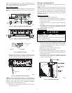
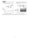
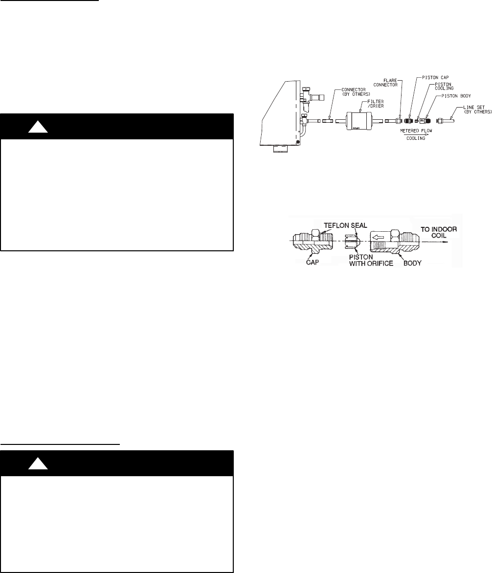
38HDF Units:
1. Assemble the connector tube to the factory supplied filter
drier by:
a. Braze the field supplied connector to the inlet of the
filter drier (see Fig. 17)
b. Braze the factory supplied flare connector to the outlet
end of the filter drier (see Fig.17)
A09499
Fig. 17 -- 38HDF018--036 Connector Tube Assembly
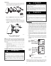
2. Assemble the Accurator body (see Fig. 18) using the correct
factory supplied piston (refer to Table 7) .
NOTE: Arrow on AccuRater body points in free flow direction, away from the
indoor coil.
A09501
Fig. 18 -- AccuRater (bypass type) Metering Device
Components
3. Attach the complete Accurator assembly to the flare connec-
tion end of the filter drier
4. Braze the completed filter drier/Accurator assembly to the
liquid service valve.
5. Connect the field supplied line set to the filter drier/Accura-
tor assembly and the suction valve. A sweat connection is
required at the suction valve and flare connection is required
for the mixed phase line.
6. Insulate any exposed areas between the line set and the li-
quid valve.