


17
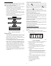
A
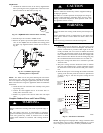
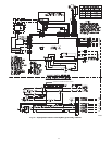
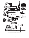
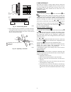
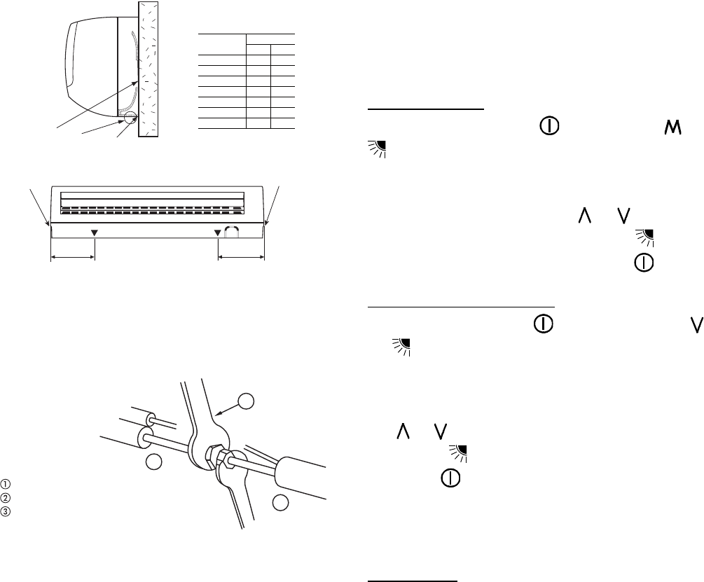
Wall
Hanging
Bracket
Hook
Hole
Retainer
Clip
Retainer
Clip
B
UNIT SIZE
DIMENSION
AB
40QNC01824 13.4 10.6
40QNC030 12.2 12.2
40QNC036 12.2 12.2
40QNQ018 13.4 10.6
40QNQ024 13.4 10.6
40QNQ030 12.2 12.2
40QNQ036 12.2 12.2
A08365
Fig. 29 -- Wall Mounting Details
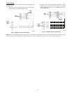
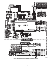
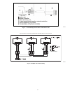
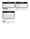
8. If the refrigerant piping connections are located outside the
wall, tighten the flare connections as shown in Fig. 30. Insu-
late all exposed refrigerant lines and secure to the wall and
fill any void spaces in the hole.
Adjustable wrench or torque wrench
Outdoor end
Indoor end
3
1
2
A07201
Fig. 30 -- Tightening Connections
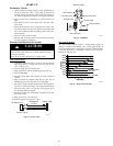
USER INTERFACE
The indoor unit includes a wireless remote control to operate the
unit (an Owner’s Manual is supplied with the unit). If you have
two units installed in the same space and they need to work
independently, the remote controls and the units need to be
configured as follow:
Unit Configuration
Turn the unit off by pressing the . Press and hold the and
buttons of the remote control for more than 5 seconds. The
display will be cleared and the time segments will display the first
configuration item (rAdr=remote address) and the temperature
segments will display the default value of this configuration item
(Ab=control of both indoor units). Press
and to change the
default value to the new value of (a) or (b). Press the
button to
transmit the new configuration to the unit. Press the
button to
leave the configuration menu.
Remote Control Configuration
Turn the unit off by pressing the button. Press and hold the
and buttons for more than 5 seconds. The display will be
cleared and the time segments will display the first configuration
item (CH=remote address) and the temperature segments will
display the default value of this configuration item (Ab=control of
both indoor units).
Press
and to change the default value to the new value of (a)
or (b). Press the
button to transmit the new configuration to the
unit. Press the
button to leave the configuration menu.
NOTE: When 30 seconds have elapsed and no buttons have been
pressed, the remote control will automatically exit the
configuration menu and resume its normal operation.
A wall mounted control or zone manager can be used to control a
unit or multiple units.
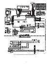
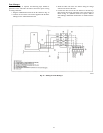
Wired Control
If a wall mounted wired control is required the following steps
should be performed at the same time the indoor control and power
wiring are being connected:
1. Unplug the connector on J5.
2. Remove the wire harness from the wired control box
3. Plug one end of the wire harness into the J5 connector on
the board
4. Route the other end of the wire harness to the back of the
unit along the low voltage wiring
5. Connect the other end of the wire harness to the field sup-
plied wiring between the indoor unit and the wired control
as shown in wired control installation instructions and Fig.
31.