


11
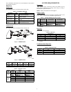
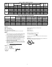
Table 10 – 38HDF / 38QRF Electrical Data
38HDF /
38QRF
UNIT
SIZE
V --- P H --- H z
VOLTAG E RANGE*
COMPRESSOR OUTDOOR FAN MOTOR
MIN CKT
AMPS
FUSE/
HACR
BKR
AMPS
RLA LRA FLA NEC Hp kW Out
Min Max
018 208/230---1---60 187 253 9.0 48.0 0.80 0.125 0.09 12.1 20
024 208/230---1---60 187 253 12.8 58.3 0.80 0.125 0.09 16.8 25
030 208/230---1---60 187 253 14.1 73.0 1.50 0.25 0.19 18.4 30
035
208/230---1---60 187 253 16.7 79.0 1.50 0.25 0.19 22.3 35
208/230---3---60 187 253 10.4 79.0 1.50 0.25 0.19 14.5 20
460 --- 3 --- 60 414 506 5.8 79.0 0.80 0.25 0.19 8.7 15
036
208/230---1---60 187 253 17.9 112.0 1.45 0.25 0.19 23.8 40
208/230---3---60 187 253 13.2 88.0 1.45 0.25 0.19 18.0 30
460 --- 3 --- 60 414 506 6.0 44.0 0.80 0.25 0.19 8.3 15
Table 11 – 40QNC, QNQ Fan Coil Electrical Data
UNIT SIZE V --- P H --- H z
VOLTAG E RANGE* FAN POWER
Min Max FLA
Motor Power
(Watts)
MIN CKT
AMPS
FUSE/CKT
BKR AMPS
40QNC01824 208/230---1---60 187 253 0.38 64 0.48 15
40QNC030 208/230---1---60 187 253 0.38 74 0.48 15
40QNC036 208/230---1---60 187 253 0.44 74 0.55 15
40QNQ018 208/230---1---60 187 253 0.38 64 0.48 15
40QNQ024 208/230---1---60 187 253 0.38 64 0.48 15
40QNQ030 208/230---1---60 187 253 0.38 74 0.48 15
40QNQ036 208/230---1---60 187 253 0.44 74 0.55 15
LEGEND:
FLA --- Full Load Amps
LRA --- Locked Rotor Amps
NEC --- National Electrical Code
RLA ---RatedLoadAmps(compressor)
* P ermissible limits of the voltage range at which the unit will operate
satisfactorily
NOTES:
1. Control circuit is 24---V on all units and requires external power
source. Copper wire must be used from service disconnect to unit.
2. All motors/compressors contain internal overload protection.
3. In co mpliance wi th NEC (USA Standard) requirements for multimo-
tor and combination load equipment (refer to NEC Articles 430 and
440), the over current protective device for the unit shall be f use.
4. Motor RLA valu es are established in accordance with UL (Under-
writers’ Laboratories) Standard 465 (USA Standard).
5. 38QRF018---030 units are only available in single---phase voltage.
6. Unbalance d 3---Phase Supply Voltage
Never operate a motor where a phase imbalance in supply voltage is
greater than 2%. Use the following formula to determine the percent-
age of voltage imbalance:
= 100 X
max voltage deviation f rom average
voltage
average
EXAMPLE: S uppl y vol tage is 460 ---3 ---60
AB = 452v
BC = 464v
AC = 455v
Average V oltage = 452 + 464 + 455
3
=
1371
3
=
457
Determine maximum deviation from average voltage:
(AB) 457---452 = 5v
(BC) 464---457 = 7v
(AC) 457---455 = 2v
Maximum deviation is 7v.
Determinepercentageofvoltageimbalance
% of voltage imbalance = 100 x
7
57
= 1.53%
This amount of phase imbalance is satisfactory as it is below the maximum
allowable of 2%.
IMPORTANT: Contact your local electric utility company immediately if the
suppl y voltage ph ase imbalance is more than 2%.