


24
Compressor Overload —
This overload interrupts power to the compressor when
either the current or internal motor winding temperature
becomes excessive, and automatically resets when the
internal temperature drops to a safe level. This overload
may require up to 60 minutes (or longer) to reset. If the
internal overload is suspected of being open, disconnect
the electrical power to the unit and check the circuit
through the overload with an ohmmeter or continuity
tester.
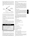
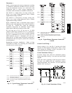
Advanced Scroll Temperature Protection (ASTP) —
A label located above the terminal box identifies Copeland
Scroll compressor models that contain this technology. See
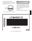
Fig. 20. Advanced Scroll Temperature Protection (ASTP) is
a form of internal discharge temperature protection, that
unloads the scroll compressor when the internal temperature
reaches approximately 149_C (300_F). At this temperature,
an internal bi--metal disk valve opens and causes the scroll
elements to separate, which stops compression. Suction and
discharge pressures balance while the motor continues to
run. The longer the compressor runs unloaded, the longer it
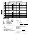
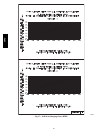
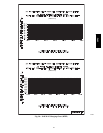
must cool before the bi--metal disk resets. See Fig. 21.
C10080
Fig. 20 -- Advanced Scroll Temperature Protection Label
0
10
20
30
40
50
60
70
80
90
100
110
120
0 10203040 6070809050
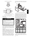
Compressor Unloaded Run Time (Minutes)*
*Times are approximate.
NOTE: Various factors, including high humidity, high ambient
temperature, and the presence of a sound blanket will
increase cool-down times.
Recommended Cooling Time*
(Minutes)
C10081
Fig. 21 -- Recommended Minimum Cool-Down Time
After Compressor is Stopped
To manually reset ASTP, the compressor should be
stopped and allowed to cool. If the compressor is not
stopped, the motor will run until the motor protector trips,
which occurs up to 90 minutes later. Advanced Scroll
Temperature Protection will reset automatically before the
motor protector resets, which may take up to 2 hours.
Start Unit
Set the space thermostat to a set point above space
temperature so that there is no demand for cooling. Close
the 38AU disconnect switch. Only the crankcase heater
will be energized.
Reset the space thermostat below ambient so that a call
for cooling is ensured.
UNIT DAMAGE HAZARD
Failure to follow this caution may result in equipment
damage.
Never charge liquid into the low-pressure side of
system. Do not overcharge. During charging or
removal of refrigerant, be sure indoor-fan system is
operating. Ensure both outdoor fan motors are
running; bypass any Motormaster function.
CAUTION
!
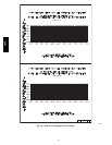
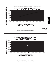
Adjust Refrigerant Charge —
Refer to Cooling Charging Charts, Fig. 23 through Fig. 28.
For applications with line lengths greater than 125 ft (38 m),
contact Carrier representative. Vary refrigerant until the
conditions of the chart are met. Note that the charging charts
are different from the type normally used. The charts are
based on charging the units to the correct subcooling for the
various operating conditions. Accurate pressure gage and
temperature sensing device are required. Connect the
pressure gage to the service port on the liquid line service
valve. Mount the temperature sensing device on the liquid
line close to the liquid line service valve, and insulate it so
that outdoor ambient temperature does not affect the reading.
Indoor airflow must be within the unit’s normal operating
range. Operate the unit for a minimum of 15 minutes.
Ensure that pressure and temperature readings have
stabilized. Plot the liquid pressure and temperature on chart
and add or reduce the charge to meet the curve. Adjust the
charge to conform with the charging chart, using the liquid
pressure and temperature to read the chart.
Using plotted operating point:
If plotted operating condition is --
Adjust charge by --
BELOW the curve REDUCE charge
ABOVE the curve ADD charge
38AU