


22
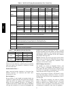
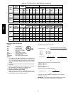
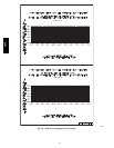
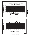
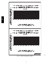
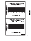
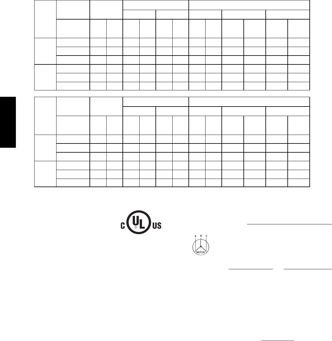
Table 10 – Unit Wire/Fuse or HACR Breaker Sizing Data
UNIT
SIZE
38AU
NOMINAL
POWER
SUPPLY
VOLT AGE
RANGE
COMPRESSOR NO C.O. orUNPWRD C.O.
No. 1 No. 2 OFM POWER SUPPLY DISCONNECT SIZE
V --- Ph --- H z Mi n Max RLA LRA RLA LRA Qty
FLA
(ea)
MCA
FUSE or
HACR
BRKR
FLA LRA
D*16
Z*16
208/230---3---60 187 253 25.0 164 25.0 164 3 1.5 60.8/60.8 80/80 63/63 337/337
460 ---3 ---60 414 506 12.2 100 12.2 100 3 0.8 29.9 40 31 206
575 ---3 ---60 518 633 9.0 78 9.0 78 3 0.7 22.4 30 23 162
D*25
Z*25
208/230---3---60 187 253 30.1 225 30.1 225 4 1.5 73.7/73.7 100/100 76/76 462/462
460 ---3 ---60 414 506 16.7 114 16.7 114 4 0.8 40.8 50 42 236
575 ---3 ---60 518 633 12.2 80 12.2 80 4 0.7 30.3 40 31 168
UNIT
SIZE
38AU
NOMINAL
POWER
SUPPLY
VOLT AGE
RANGE
COMPRESSOR w/ PWRD C.O.
No. 1 No. 2 OFM POWER SUPPLY DISCONNECT SIZE
V --- Ph --- H z Mi n Max RLA LRA RLA LRA Qty
FLA
(ea)
MCA
FUSE or
HACR
BRKR
FLA LRA
D*16
Z*16
208/230---3---60 187 253 25.0 164 25.0 164 3 1.5 65.6/65.6 90/90 68/68 342/342
460 ---3 ---60 414 506 12.2 100 12.2 100 3 0.8 32.1 40 33 208
575 ---3 ---60 518 633 9.0 78 9.0 78 3 0.7 24.1 30 25 164
D*25
Z*25
208/230---3---60 187 253 30.1 225 30.1 225 4 1.5 78.5/78.5 100/100 82/82 467/467
460 ---3 ---60 414 506 16.7 114 16.7 114 4 0.8 43 50 45 238
575 ---3 ---60 518 633 12.2 80 12.2 80 4 0.7 32 40 33 170
Legend and Notes for Table 10
LEGEND:
BRKR --- Circuit breaker
CO --- Convenient outlet
FLA --- Full Load Amps
LRA --- Locked Rotor Amps
MCA --- Minimum Circuit Amps
Protection
NEC --- National Electrical Code
PWRD CO --- Powered convenient outlet
RLA --- Rated Load Amps
UNPWR CO --- Un powered convenient outlet
NOTES:
1. In compliance with NEC requirements for multimotor and
combination load equipment (refer to NEC Articles 430 and
440), the overcurrent protective device for the unit shall be
fuse or HACR breaker. Canadian units may be fuse or circuit
breaker.
2. The MCA values are calculated in accordance with The NEC.
Article 440.
3. Motor RLA and LRA values are established in accordance
with Underwriters’ Laboratories (UL). Standard 1995.
4. The 575 --- v units are UL , Canada --- listed only.
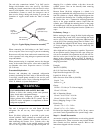
5. Unbalanced 3-Phase Supply Voltage
Never operate a motor where a phase imbalance in supply
voltage is greater than 2%. Use the following formula to de-
termine the percentage of voltage imbalance.
Example: Supply voltage is 230-3-60
% Voltage Imbalance =100 x
max voltage deviation from average voltage
averagevoltage
AB = 224 v
BC = 231 v
AC = 226 v
Average Voltage =
(224 +231 +226)
=
681
3
3
= 227
Determine m aximum deviation from average voltage.
(AB) 227 – 224 = 3 v
(BC) 231 – 227 = 4 v
(AC) 227 – 226 = 1 v
Maximum deviation is 4 v .
Determine percent of voltage imbalance.
% Voltage Imbalance =100 x
4
227
=1.76%
This amount of p h ase imbalance is satisfactory as it is below the
maximum allowable 2%.
IMPORTANT: If the supply voltage phase imbalance is more than
2%, contact your local electric utility company immediately.
38AU