


16
INDOOR
COIL CKT 2
AIRFLOW
INDOOR
COIL CKT 1
AIRFLOW
15 DIAMS
MIN
10
DIAMS
8 DIAMS
MIN
TXV
SENSING
BULB
EQUALIZER LINE
SIGHT GLASS
A LOCATION
SIGHT
GLASSES
B LOCATION
TXV
CKT 2
FILTER DRIER
A LOCATION
FILTER
DRIERS
B LOCATION
FLOW
TXV
SENSING
BULB
TXV
CKT 1
8 DIAMS
MIN
15 DIAMS
MIN
10
DIAMS
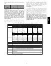
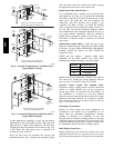
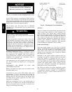
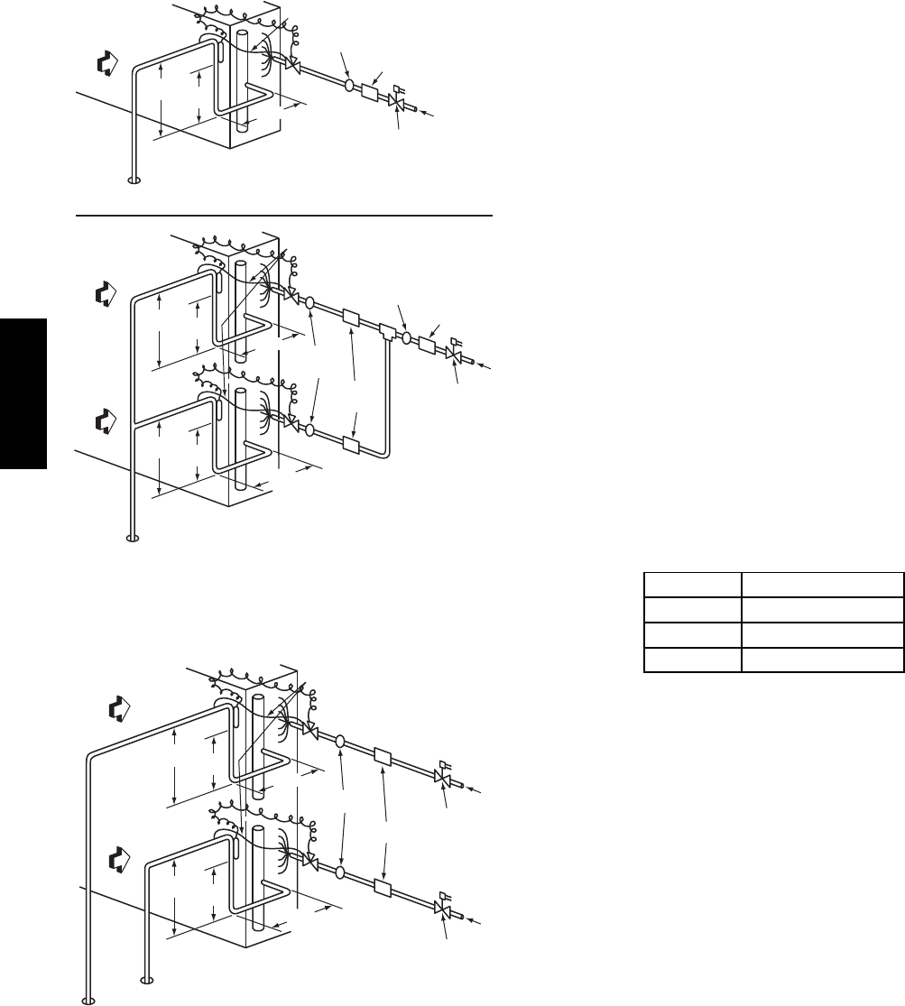
Single Circuit Coil Piping Configuration
For single compressor condensing units
Dual Circuit Coil Piping Configuration
For single compressor condensing units
15 DIAMS
MIN
10
DIAMS
8 DIAMS
MIN
INDOOR
COIL CKT
AIRFLOW
TXV
SENSING
BULB
EQUALIZER LINE
SIGHT GLASS
A LOCATION
TXV
FILTER DRIER
A LOCATION
LIQUID LINE
SOLENOID
VALVE
FLOW
LIQUID LINE
SOLENOID
VALVE
C10202
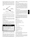
Fig. 8 -- Location of Sight Glass(es) and Filter Driers
Typical 38AUZ Systems
AIRFLOW
SUCTION
CIRCUIT 2
SUCTION
CIRCUIT 1
AIRFLOW
15 DIAMS
MIN
10
DIAMS
8 DIAMS
MIN
TXV
SENSING
BULB
EQUALIZER LINE
SIGHT
GLASSES
TXV
CKT 2
FILTER
DRIERS
LIQUID LINE
SOLENOID VALVE
CIRCUIT 2
FLOW
LIQUID LINE
SOLENOID VALVE
CIRCUIT 1
FLOW
TXV
SENSING
BULB
TXV
CKT 1
8 DIAMS
MIN
15 DIAMS
MIN
10
DIAMS
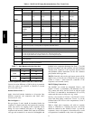
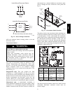
Dual Circuit Coil Piping Configuration
For two circuit condensing units
C10072
Fig. 9 -- Location of Sight Glasses and Filter Driers
Typical 38AUD Systems
In some applications, depending on space and convenience
requirements, it may be desirable to install 2 filter driers and
sight glasses in a single circuit application. One filter drier
and sight glass may be installed at A locations (see Fig. 8) or
2 filter driers and sight glasses may be installed at B
locations (see Figs. 8 and 9).
Select the filter drier for maximum unit capacity and
minimum pressure drop. Complete the refrigerant piping
from the indoor unit to the outdoor unit before opening
the liquid and suction lines at the outdoor unit.
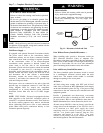
Install Liquid Line Solenoid Valve —
It is recommended that a solenoid valve be placed in the
main liquid line (see Figs. 8 & 9) between the condensing
unit and the evaporator coil. Locate the solenoid valve at the
outlet end of the liquid line, near the evaporator coil
connections, with flow direction arrow pointed at the
evaporator coil. Refer to Table 9. (A liquid line solenoid
valve is required when the liquid line length exceeds 75 ft
[23 m].) This valve prevents refrigerant migration (which
causes oil dilution) to the compressor during the off cycle, at
low outdoor ambient temperatures. Wire the solenoid in
parallel with the compressor contactor coil (see Figs. 8 & 9).
This means of electrical control is referred to as solenoid
drop control.
Solenoid drop control wiring: Control the power to the
liquid line solenoid through a Solenoid Valve Relay (SVR)
in all units. Use part number HN61PC005 (field--supplied,
installed). 38AUZ unit requires one SVR; 38AUD unit
requires two relays.
38AUD unit also requires a separate control power
transformer for the liquid solenoid valve loads. Select
transformer part number according to unit power supply.
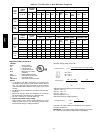
Unit Po w er Transformer Part #
208/230 HT01BD202
460 HT01BD702
575 HT01BD902
Mount the SVR (and transformer TRAN3 when used) in
unit control box. Connect per wiring schematic label on
unit or per Fig. 29 (38AUZ) or Fig. 30 (38AUD).
Capacity Control Liquid Line Solenoid Valve:
Evaporator capacity staging control via direct thermostat
control of a liquid solenoid valve on the evaporator’s
second stage circuit is not possible with 38AU models. If
this installation is a retrofit for a unit that included
automatic pressure--operated unloading, check the existing
thermostat and liquid solenoid valve wiring for possible
direct thermostat control of a solenoid valve; re--wire per
Figs. 17 or 18 and 29 or 30.
Selecting an Accumulator –
Because all 38AU models use scroll compressors, an
accumulator is not required. If an accumulator is to be
added, check the accumulator manufacturer’s literature
carefully for indication of its suitability for use with
R--410A; look for minimum working pressure of 200 psig
(1380 kPa). Select the accumulator first on the basis of its
cataloged minimum capacity (tons) to ensure oil return from
the accumulator, then on tube size or holding capacity.
Make Piping Connections —
Piping connections at the 38AU unit are ball valves with
stub tube extensions. Do not open the unit service valves
until all interconnecting tube brazing has been completed.
38AU