


18
Step 7 — Complete Electrical Connections
ELECTRICAL SHOCK HAZARD
Failure to follow this warning could result in personal
injury or death.
Do not use gas piping as an electrical ground. Unit
cabinet must have an uninterrupted, unbroken electrical
ground to minimize the possibility of personal injury if
an electrical fault should occur. This ground may consist
of electrical wire connected to unit ground lug in control
compartment, or conduit approved for electrical ground
when installed in accordance with NEC (National
Electrical Code); ANSI/NFPA 70, latest edition (in
Canada, Canadian Electrical Code CSA [Canadian
Standards Association] C22.1), and local electrical
codes.
!
WARNING
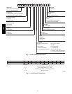
NOTE: Check all factory and field electrical connections
for tightness. Field-supplied wiring shall conform with the
limitations of 63°F(33°C) rise.
Field Power Supply —
If equipped with optional Powered Convenience Outlet:
The power source leads to the convenience outlet’s
transformer primary are not factory connected. Installer
must connect these leads according to required operation
of the convenience outlet. If an always-energized
convenience outlet operation is desired, connect the
source leads to the line side of the unit-mounted
disconnect. (Check with local codes to ensure this method
is acceptable in your area.) If a de-energize via unit
disconnect switch operation of the convenience outlet is
desired, connect the source leads to the load side of the
unit disconnect. On a unit without a unit-mounted
disconnect, connect the source leads to compressor
contactor C and indoor fan contactor IFC pressure lugs
with unit field power leads..
Field power wires are connected to the unit at line-side
pressure lugs on compressor contactor C and TB1 (see
wiring diagram label for control box component
arrangement) or at factory-installed option non-fused
disconnect switch. Max wire size is #4 AWG (copper
only).
NOTE: TEST LEADS - Unit may be equipped with short
leads (pigtails) on the field line connection points on
contactor C or optional disconnect switch. These leads are
for factory run-test purposes only; remove and discard
before connecting field power wires to unit connection
points. Make field power connections directly to line
connection pressure lugs only.
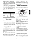
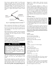
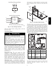
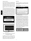
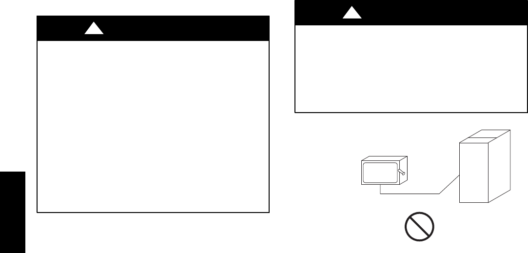
FIRE HAZARD
Failure to follow this warning could cause in personal
injury, death and/or equipment damage.
Do not connect aluminum wire between disconnect
switch and condensing unit. Use only copper wire.
(See Fig. 11.)
!
WARNING
COPPER
WIRE ONLY
ELECTRIC
DISCONNECT
SWITCH
ALUMINUM
WIRE
A93033
Fig. 11 -- Disconnect Switch and Unit
Units Without Factory-Installed Disconnect —
When installing units, provide a disconnect switch per
NEC (National Electrical Code) of adequate size.
Disconnect sizing data is provided on the unit informative
plate. Locate on unit cabinet or within sight of the unit per
national or local codes. Do not cover unit informative
plate if mounting the disconnect on the unit cabinet.
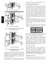
Units with Factory-Installed Disconnect —
The factory-installed option disconnect switch is located
in a weatherproof enclosure located under the main
control box. The manual switch handle is accessible
through an opening in the access panel.
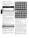
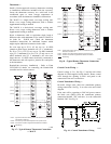
All Units —
All field wiring must comply with NEC and all local
codes. Size wire based on MCA (Minimum Circuit Amps)
on the unit informative plate. See Fig. 12 for power wiring
connections to the unit contactor and terminal block and
equipment ground.
Provide a ground-fault and short-circuit over-current
protection device (fuse or breaker) per NEC Article 440
(or local codes). Refer to unit informative data plate for
MOCP (Maximum Over-current Protection) device size.
All units except 208/230-v units are factory wired for the
voltage shown on the nameplate. If the 208/230-v unit is
to be connected to a 208-v power supply, the control
transformer must be rewired by moving the black wire
with the
1
/
4
-in. female spade connector from the 230-v
connection and moving it to the 208-v
1
/
4
-in. male
terminal on the primary side of the transformer. Refer to
unit label diagram for line-side information.
38AU