


20
B50HJ542739
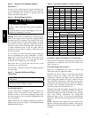
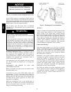
Maximum Continuous use : 8 Amps 24/7
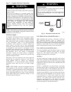
Convenience Outlet Utilization
NOTICE
C10207
Fig. 15 -- Convenience Outlet Utilization Notice Label
Test the GFCI receptacle by pressing the TEST button on
the face of the receptacle to trip and open the receptacle.
Check for proper grounding wires and power line phasing
if the GFCI receptacle does not trip as required. Press the
RESET button to clear the tripped condition.
Fuse on power type: The factory fuse is a Bussman
“Fusetron” T-15, non-renewable screw-in (Edison base)
type plug fuse.
ELECTRICAL OPERATION HAZARD
Failure to follow this warning could result in personal
injury or death.
Using unit-mounted convenience outlets: Units with
unit-mounded convenience outlet circuits will often
require that two disconnects be opened to de-energize
all power to the unit. Treat all units as electrically
energized until the convenience outlet power is also
checked and de-energization is confirmed. Observe
National Electrical Code Article 210, Branch Circuits,
for use of convenience outlets.
!
WARNING
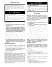
Installing Weatherproof Cover: A weatherproof while in
use cover for the factory installed convenience outlets is
now required by UL standards. This cover cannot be
factory mounted due its depth; it must be installed at unit
installation. For shipment, the convenience outlet is
covered with a blank cover plate.
The weatherproof cover kit is shipped in the unit’s control
box. The kit includes the hinged cover, a backing plate
and gasket.
DISCONNECT ALL POWER TO UNIT AND
CONVENIENCE OUTLET.
Remove the blank cover plate at the convenience outlet;
discard the blank cover.
Loosen the two screws at the GFCI duplex outlet, until
approximately
1
/
2--
in (13 mm) under screw heads are
exposed. Press the gasket over the screw heads. Slip the
backing plate over the screw heads at the keyhole slots
and align with the gasket; tighten the two screws until
snug (do not overtighten).
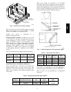
Mount the weatherproof cover to the backing plate as
shown in Fig. 16. Remove two slot fillers in the bottom of
the cover to permit service tool cords to exit the cover.
Check for full closing and latching.
C09022
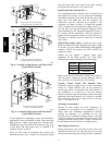
Fig. 16 -- Weatherproof Cover Installation
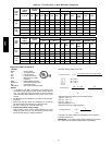
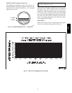
All Units —
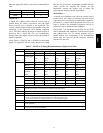
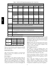
Voltage to compressor terminals during operation must be
within voltage range indicated on unit nameplate. See
Tables 10 and 11. On 3-phase units, voltages between
phases must be balanced within 2% and the current within
10%. Use the formula shown in the legend for Tables 10
and 11, Note 5 (see page 22) to determine the percent of
voltage imbalance. Operation on improper line voltage or
excessive phase imbalance constitutes abuse and may
cause damage to electrical components. Such operation
would invalidate any applicable Carrier warranty.
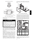
Field Control Wiring —
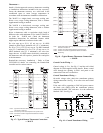
38AU unit control voltage is 24 v. See Fig. 29 (38AUZ)
and Fig. 30 (38AUD) for typical field control connections
and the unit’s label diagram for field-supplied wiring
details. Route control wires to the 38AU unit through the
opening in unit’s end panel to the connections terminal
board in the unit’s control box.
Remainder of the system controls connection will vary
according to the specific construction details of the indoor
section (air handler or packaged fan coil). Fig. 17
(38AUZ) and Fig. 18 (38AUD) depict typical connections
to a Carrier 40RU fan coil unit. Plan for field connections
carefully and install control wiring correctly per the
project plan. Additional components and supplemental
transformer accessory may be required.
The 38AU unit requires an external temperature control
device. This device can be a thermostat (field-supplied) or
a PremierLink controller (available as a field-installed
accessory, for use on a Carrier Comfort Network or as a
stand alone control).
38AU