


21
Thermostat —
Install a Carrier-approved accessory thermostat according
to installation instructions included with the accessory.
Locate the thermostat accessory on a solid wall in the
conditioned space to sense average temperature in
accordance with the thermostat installation instructions.
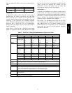
The 38AUZ is a single-circuit, two--stage cooling unit.
Select a two—stage cooling thermostat, with or without
supplemental heating as needed.
The 38AUD is a dual--circuit, two-stage cooling unit.
Select a two—stage cooling thermostat, with or without
supplemental heating as needed.
Select a thermostat cable or equivalent single leads of
different colors with minimum of five leads for 38AUZ or
six leads for 38AUD unit. Check the thermostat
installation instructions for additional features which
might require additional conductors in the cable.
For wire runs up to 50 ft. (15 m), use no. 18 AWG
(American Wire Gage) insulated wire (35C minimum).
For50to75ft.(15to23m),useno.16AWGinsulated
wire (35C minimum). For over 75 ft. (23 m), use no. 14
AWG insulated wire (35C minimum). All wire sizes
larger than no. 18 AWG cannot be directly connected to
the thermostat and will require a junction box and splice
at the thermostat.
PremierLink (accessory installation) – Refer to Form
33CS-58SI for details on connecting the PremierLink
controller and its various sensors.
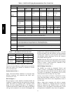
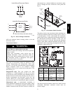
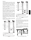
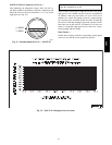
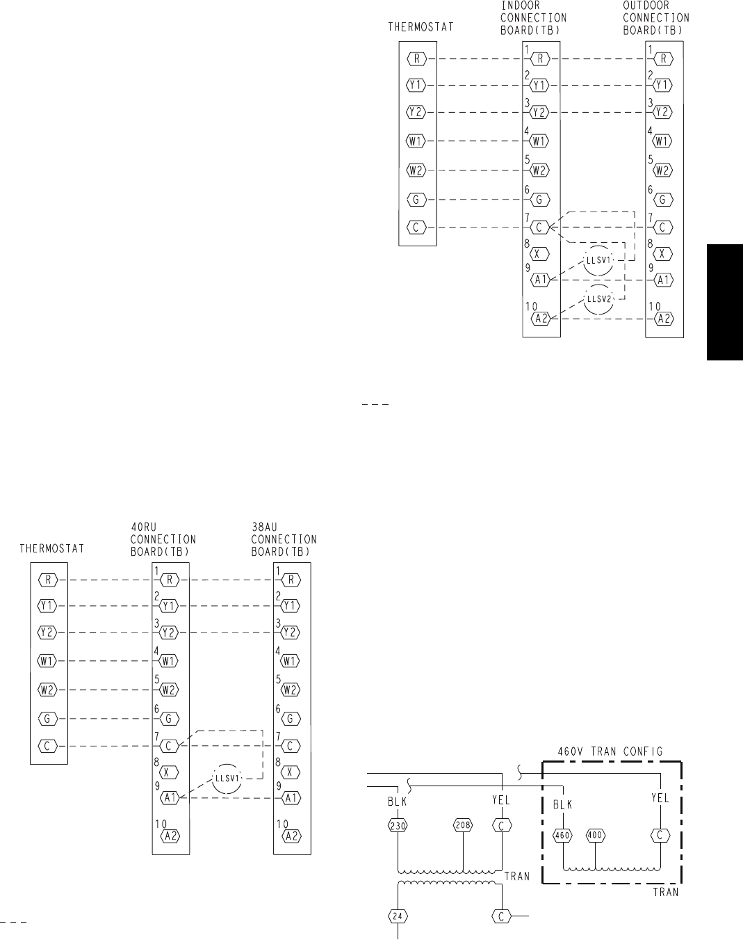
Note 1: Typical multi-function marking. Follow manufacturer’s configuration
instructions to select Y2.
Note 2: Connect only if thermostat requires 24-vac power source.
Note 3: Connect W1 and W2 if supplemental heaters are installed
Field Wiring
(Note 1)
(Note 2)
(Note 3)
(Note 3)
C10208
Fig. 17 -- Typical Remote Thermostat Connections
— 38AUZ
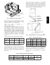
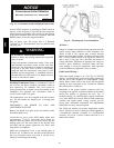
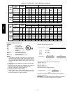
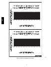
Note 1: Typical multi-function marking. Follow manufacturer’s configuration
instructions to select Y2.
Note 2: Connect only if thermostat requires 24-vac power source.
Note 3: Connect W1 and W2 if supplemental heaters are installed
Field Wiring
(Note 1)
(Note 2)
(Note 3)
(Note 3)
C10078
Fig. 18 -- Typical Remote Thermostat Connections
— 38AUD
Control Circuit Wiring —
Control voltage is 24 v. See Fig. 12 and the unit’s label
diagram for field--supplied wiring details. Route control
wires through the opening in unit’s end panel to the
connection in the unit’s control box.
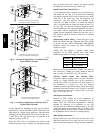
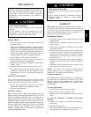
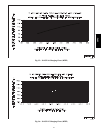
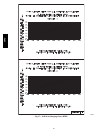
Control Transformer Wiring —
On multi voltage units, check the transformer primary
wiring connections. See Fig. 19 or refer to the unit’s label
diagram.
If the unit will be operating at 208-3-60 power, remove
the black wire (BLK) from the transformer primary
connection labelled “230” and move it to the connection
labelled “208”. See Fig. 19.
C10079
Fig. 19 -- Control Transformer Wiring
38AU