


14
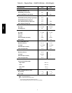
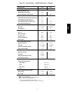
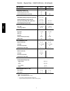
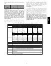
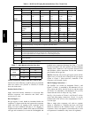
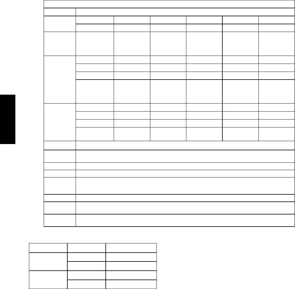
Table 6 – 38AUD 16-25 Piping Recommendations (Two-Circuit Unit)
NOTE: 38AUD requires TWO sets of refrigeration piping
R -410A Equivalent Length
Ft 0-38 38-75 75-113 113-150 150-188
m 0-12 12-23 23-34 34-46 46-57
Model
Linear Length
Ft 0-25 25-50 50-75 75-100 100-125
m 0-8 8-15 15-23 23-30 30-38
38AUD*16 Liquid Line
1
/
2
1
/
2
1
/
2
1
/
2
1
/
2
Max Lift 25 50 75 100 125
Suction Line
7
/
8
1
1
/
8
1
1
/
8
1
1
/
8
1
1
/
8
Charge ea. (lbs)
Novati on 11.7 13.8 15.7 17.6 19.6
RTPF 21.7 23.8 25.7 27.6 29.6
38AUD*25 Liquid Line
1
/
2
1
/
2
1
/
2
5
/
8
1
/
2
5
/
8
1
/
2
5
/
8
Max Lift 25 50 54 75 60 99 46 95
Suction Line 1
1
/
8
1
1
/
8
1
1
/
8
1
1
/
8
1
3
/
8
1
3
/
8
Charge (lbs) 1
2
19.3
18.3
21.0
20.3
23.0
22.0
26.0
25.0
25.9
24.9
29.7
28.7
28.0
27.0
32.7
31.7
Legend:
Equivalent
Length
Equivalent tubing length, including effects of refrigeration specialties devices
Linear Length Typical linear tubing length (50% added to linear to define Equivalent Length for this table)
Liquid Line Tubing size, inches OD.
Max Lift Maximum liquid lift (indoor unit ABOVE outdoor unit only), at maximum permitted liquid line pressure drop —
S Linear Length Lessthan 75 ft (23 m): Minimum 2.0°F subcooling entering TXV
S Linear Length Greater than 75 ft(23m): Minimum 0.5°F subcooling entering TXV
Suction Line Tube size, inches OD
Charge Charge Quantity, lbs. Calculated for both liquid line sizes (where applicable), but only with larger suction line size
(where applicable)
NOTE: For applications with equivalent length greater than 188 ft (57 m) and/0r linear length greater than 125 ft (38 m),
contact your local Bryant representative.
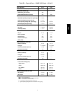
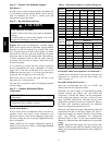
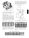
Table 7 – 38AU Maximum Suction Pipe Size
Model: Unit Size Maximum Tube Size
38AUZ
16 1
5
/
8
25 1
5
/
8
38AUD
16 1
5
/
8
25 1
5
/
8
Vertical Separation (outdoor unit above indoor unit) –
Vertical elevation difference of 200 ft (60 m) is permitted
when the outdoor unit (38AUZ or 38AUD) is located
above the indoor unit.
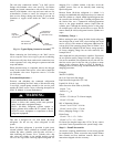
Insulate Suction Lines —
Apply closed-cell tubular insulation to all suction lines
between evaporator coil connection and 38AU unit’s
suction service valve.
Hot Gas Bypass —
Hot gas bypass, if used, should be introduced before the
evaporator. (A bypass route that also bypasses the evaporator
circuit may lead to oil trapping in the evaporator circuit
during low load conditions and then to oil slugging as
evaporator load increases.) Model 38AU units do not include
a hot gas stub connection; a tee must be field-supplied and
installed in the compressor discharge line. Run a
1
/
2
-in OD
line between outdoor unit and evaporator coil inlet. Install an
Auxiliary Side Connector at the evaporator between TXV
and distributor (follow instructions for the side connector
part). Insulate the hot gas line.
38AUD: Generally only one hot gas bypass system will be
applied on a two-circuit unit. Connect the hot gas bypass
system to Circuit 1 (first-on/last-off, connected to the
evaporator coil’s bottom circuit).
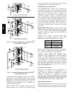
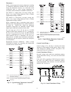
38AUD Piping Connections —
The 38AUD’s two circuits are designated Circuit 1 and
Circuit 2. Circuit 1 is controlled by the thermostat’s Y1 (or
TC1) contact and will be the first circuit on and last circuit
off. Circuit 2 is controlled by the thermostat’s Y2 (or TC2)
contact and this circuit is always the “lag” circuit.
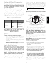
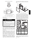
See Fig. 6 for location of Circuit 1 and Circuit 2 service
valves and field piping connections. Circuit 1 is on the
left-hand side of the service valve compartment; Circuit 2
is on the right.
When a single piece evaporator coil with two separate
circuits is connected to a 38AUD, the lower coil circuit
should be connected to the 38AUD’s Circuit 1 so that the
evaporator’s lower coil segment is first-on/last-off (to avoid
re-evaporation of condensate on dry lower coil segments).
38AU