


12
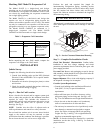
Step 3 — Prepare Unit Mounting Support
Slab Mount —
Provide a level concrete slab that extends a minimum of 6
in. (150 mm) beyond unit cabinet. Install a gravel apron in
front of condenser coil air inlet to prevent grass and
foliage from obstructing airflow.
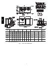
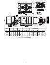
Step 4 — Rig and Mount the Unit
UNIT DAMAGE HAZARD
Failure to follow this caution may result in equipment
damage.
All panels must be in place when rigging. Unit is not
designed for handling by fork truck.
CAUTION
!
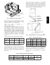
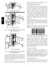
Rigging: These units are designed for overhead rigging.
Refer to the rigging label for preferred rigging method.
Spreader bars are not required if top crating is left on the
unit. All panels must be in place when rigging. As further
protection for coil faces, plywood sheets may be placed
against the sides of the unit, behind cables. Run cables to
a central suspension point so that the angle from the
horizontal is not less than 45 degrees. Raise and set the
unit down carefully.
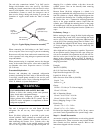
If it is necessary to roll the unit into position, mount the
unit on longitudinal rails, using a minimum of 3 rollers.
Apply force to the rails, not the unit. If the unit is to be
skidded into position, place it on a large pad and drag it
by the pad. Do not apply any force to the unit.
Raise from above to lift the unit from the rails or pad
when unit is in its final position.
After the unit is in position, remove all shipping materials
and top crating.
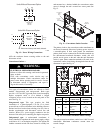
Step 5 — Complete Refrigerant Piping
Connections
IMPORTANT: Do not bury refrigerant piping
underground.
IMPORTANT: A refrigerant receiver is not provided
with the unit. Do not install a receiver.
Provide Safety Relief —
If local codes dictate an additional safety relief device,
purchase locally and install locally. Installation will
require the recovery of the factory shipping charge before
the factory tubing can be cut and the supplemental relief
device is installed.
Model 38AUD has two separate refrigeration systems. If
required, each circuit will require a field-supplied/installed
supplemental relief device.
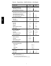
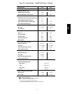
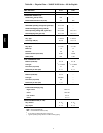
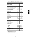
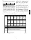
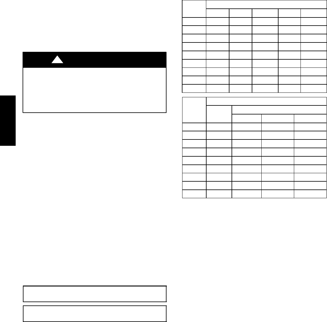
Table 4 – Equivalent Lengths for Common Fittings (ft)
Nominal
Tube OD
Elbows
90° Std 90° Lrad 90° Street 45° Std 45 ° Street
3
/
8
1.3 0.8 2.2 0.6 1
1
/
2
1.4 0.9 2.3 0.7 1.1
5
/
8
1.6 1 2.5 0.8 1.3
3
/
4
1.8 1.2 2.9 0.9 1.5
7/
8
2 1.4 3.2 0.9 1.6
1
1
/
8
2.6 1.7 4.1 1.3 2.1
1
3
/
8
3.3 2.3 5.6 1.7 3
1
5
/
8
4 2.6 6.3 2.1 3.4
2
1
/
8
5 3.3 8.2 2.6 4.5
Nominal
Tube OD
Tees
Branch
Flow
Straight-Thru
No Reduct Reduce 25% Reduce 50%
3
/
8
2.6 0.8 1.1 1.3
1
/
2
2.7 0.9 1.2 1.4
5
/
8
3 1 1.4 1.6
3
/
4
3.5 1.2 1.7 1.8
7/
8
4 1.4 1.9 2
1
1
/
8
5 1.7 2.3 2.6
1
3
/
8
7 2.3 3.1 3.3
1
5
/
8
8 2.6 3.7 4
2
1
/
8
10 3.3 4.7 5
Check 38AU Model with Evaporator Coil Connections —
Confirm before installation of unit that the evaporator coil
connections are consistent with this 38AU model. See
Table 3 on page 11.
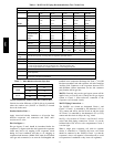
Determine Refrigerant Line Sizes —
Select the recommended line sizes for 38AUZ and
38AUD unit from the appropriate tables.
Determine the linear length of interconnecting piping
required between the outdoor unit and indoor unit
(evaporator). Consider and identify also the arrangement
of the tubing path (quantity and type of elbows in both
lines), liquid line solenoid size, filter drier and any other
refrigeration specialties located in the liquid line. Refer to
the indoor unit installation instructions for additional
details on refrigeration specialties devices.
Determine equivalent line length adjustments for path and
components and add to linear line lengths. See Table 4,
Equivalent Lengths for Common Fittings, for usual fitting
types. Also identify adjustments for refrigeration
specialties. Refer to Part 3 of the Carrier System Design
Manual for additional data and information on equivalent
lengths.
NOTE: Equivalent line lengths will vary based on tube
diameter. Calculate equivalent line length for each pipe by
adding equivalent length adjustments to linear lengths for
each pipe.
38AU