


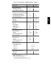
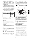
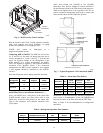
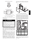
15
Circuit 1
Connections
Circuit 2
Connections
CKT
1
CKT
1
CKT
2
CKT
2
C10355
Fig. 6 -- 38AUD Service Valve Locations
Plan the Circuit 1 and Circuit 2 tubing segments carefully,
mark each segment and check constantly as piping
systems are assembled to avoid piping errors.
38AUD unit cannot be field-piped as a
single-circuit/tandem system.
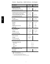
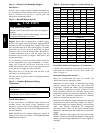
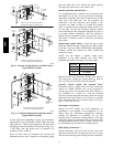
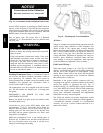
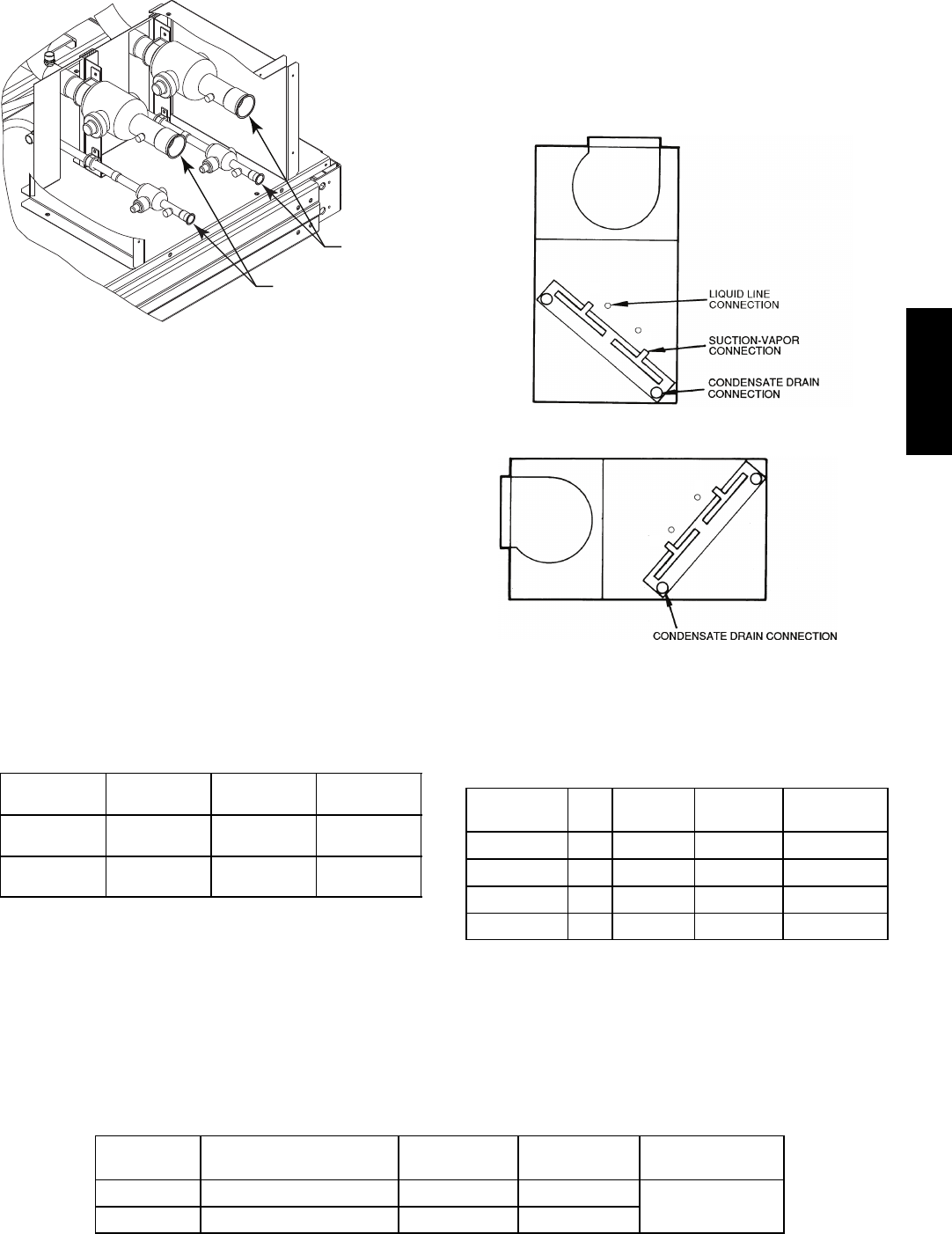
Connecting 40RU to 38AUD: The 40RU fan coil in sizes
16, 25 and 28 is a face-split coil design that also has its
circuits designated as 1 and 2. See Fig. 7. Note that the
lower coil segment changes as the arrangement of the
40RU changes. In a vertical arrangement, the 40RU’s
lower coil segment is segment 2; this segment should be
connected to the 38AUD’s Circuit 1. In a horizontal
arrangement, the 40RU’s lower segment is now segment
1; this segment should be connected to the 38AUD’s
Circuit 1.
Note that refrigerant suction piping should be insulated.
40RU
Arrangement
Cooling
Stage
40RU Coil
Segment
Connect to
38AUD
Vertical
Y1
Y2
2
1
Circuit 1
Circuit 2
Horizontal
Y1
Y2
1
2
Circuit 1
Circuit 2
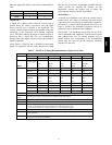
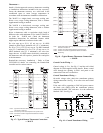
Install Filter Drier(s) and Moisture Indicator(s) —
Every unit MUST have a filter drier in the liquid line.
38AUD models require two filter driers (one in each
liquid line). Locate the filter drier(s) at the indoor unit,
close to the evaporator coil’s thermal expansion valve
(TXV) inlets.
38AU units include one (38AUZ) or two (38AUD)
Puron-duty filter drier(s), shipped in cartons attached to
the unit basepan. Remove the filter drier(s) and prepare to
install in the liquid line(s) at the evaporator coil. Do not
remove connection fitting plugs until ready to connect and
braze the filter drier into the liquid line position.
FIRST ON/LAST OFF = 2
VERTICAL INSTALLATION
FIRST ON/LAST OFF = 1
HORIZONTAL INSTALLATION
1
2
2
1
C10071
Fig. 7 -- Typical Evaporator Coil Connections (40RU)
Table 8 – Puron-duty Filter Drier(s)
Model-Size Qty
Liquid
Line OD
Desiccant
Volume
Part
Number Ref
38AUZ*16 1
5
/
8
-in 30 cu. in. KH43LG087
38AUZ*25 1
5
/
8
-in 30 cu. in. KH43LG087
38AUD*16 2
1
/
2
-in 16 cu. in. KH43LG085
38AUD*25 2
1
/
2
-in 16 cu. in. KH43LG085
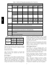
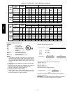
Installation of liquid line moisture indicating sightglass in
each circuit is recommended. Locate the sightglass(es)
between the outlet of the filter drier and the TXV inlet.
Refer to Table 9 for recommendations on refrigeration
specialties.
Table 9 – Refrigerant Specialties Part Numbers.
LIQUID LINE
SIZE ( in.)
LIQUID LINE
SOLENOID VALVE (LLSV)
LLSV
COIL
SIGHT
GLASS
FILTER
DRIER
1
/
2
EF680035 EF680037 KM680004
provided with unit
see Table 8
5
/
8
EF680036 EF680037 KM680005
38AUD units require TWO sets of parts.
38AU