47
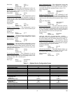
Next Unoccupied Time
— This variable displays the time of
day when the next unoccupied period is scheduled to begin.
This point is read in conjunction with the next unoccupied day
to allow the user to know the next time and day when the zone
will become unoccupied. If the zone controller is following a
global schedule this point will remain at default.
NOTE: If the current mode is unoccupied, this point makes
reference to the next unoccupied period and, in most cases,
may not be the same as the current unoccupied start time.
Next Unoccupied
Time: Display Range 00:00 to 24:00
Default Value 0:00
Network Access None
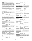
Last Unoccupied Day
— This variable displays the last day
when the zone changed from occupied to unoccupied mode.
This point is read in conjunction with the last unoccupied time
to allow the user to know the last time and day when the zone
became unoccupied. If the zone controller is following a global
schedule this point will remain at default.
Last Unoccupied
Day: Display Range MON, TUE, WED,
THU, FRI, SAT, SUN
Default Value No display (Blank)
Network Access None
Last Unoccupied Time
— This variable displays the last time
of day when the zone changed from occupied to unoccupied
mode. This point is read in conjunction with the last unoccu-
pied day to allow the user to know the last time and day when a
zone became unoccupied. If the zone controller is following a
global schedule this point will remain at default.
Last Unoccupied
Time: Display Range 00:00 to 24:00
Default Value 0:00
Network Access None
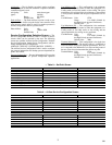
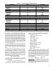
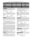
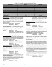
ZONE AIR BALANCE/COMMISSIONING TABLE —
The Zone Air Balance/Commissioning Table is used to display
the air balance variables. See Table 15.
Commissioning Mode
— This variable is used to put the zone
controller into the commissioning mode. Force this point to en-
able. The zone controller will be ready to accept a command to
perform the tests and functions on this screen.
NOTE: Commissioning mode will automatically be dis-
abled after one hour.
Commissioning
Mode: Display Range Dsable/Enable
Default Value Dsable
Network Access Read /Write
Damper Actuator/Transducer Calibration
— The Damper
Actuator Transducer calibration is the first calibration which
should be performed on a newly installed actuator. The zone
controller will command the actuator to close and read the
feedback potentiometer to determine the zero position of the
damper. It will then command the damper to fully open. The
zone controller will read the potentiometer to determine the
maximum open position. Damper positions from closed to
maximum open will be scaled to read 0 to 100% for the damp-
er position.
The zone controller will then close the damper and open it
once more to zero calibrate the airflow sensor. The entire
calibration procedure can take up to 3 minutes. If the damper
fails the test or the airflow calibration is unable to be complet-
ed, the Auto-Calibration point will indicate an Alarm.
Damper Actuator
Transducer
Calibration: Display Range Dsable/Enable
Default Value Dsable
Network Access Read /Write
Maximum Cooling Airflow Calibration
— By enabling the
Maximum Cooling Airflow Calibration, the Maximum Cool-
ing Airflow from the set point schedule will be made the Air-
flow CFM Set Point. The zone controller will modulate the
damper to control to this set point. The actual airflow, damper
position, and velocity pressure readings will be displayed.
If the set point is not correct, it may be changed from this
screen by forcing the airflow set point to the desired value. The
value will be written to the set point schedule in the Maximum
Cool CFM set point, and the zone controller will begin to con-
trol to the new value.
The airflow can be measured using test and balance equip-
ment and compared to the actual reading on the screen. If the
value measured requires adjustment to the value on the screen,
force the value on the screen to the value measured. The zone
controller will take the value and calculate a new calibration
gain which will be shown at the bottom of the screen. The new
value will be automatically loaded into the Service Configura-
tion table.
Maximum Cooling
Airflow
Calibration: Display Range Dsable/Enable
Default Value Dsable
Network Access Read /Write
Minimum Cooling Airflow Calibration
— Enabling the Min-
imum Cooling Airflow Calibration will cause the airflow CFM
set point to change to the Minimum Cooling set point. The ac-
tual airflow, damper position, and velocity pressure readings
will be displayed.
If the set point is not correct, it may be changed from this
screen by forcing the Airflow set point to the desired value.
The value will be written to the set point schedule in the Mini-
mum Cool CFM set point, and the zone controller will begin to
control to the new value.
The airflow can be measured using test and balance equip-
ment and compared to the actual reading on the screen. If the
value measured requires adjustment to the value on the screen,
force the value on the screen to the value measured. The zone
controller will take the value and calculate a new offset.
The Offset configuration is included for precision applica-
tions where the minimum airflow is critical and not zero. The
Offset configuration should not be used to zero the airflow
transducer since an auto zero test is included in the normal
function of the zone controller and is automatically performed
each time the equipment fan is disabled (or every 72 hours for
systems which run the fan continuously). After performing air
balance testing using the Air Balance Maintenance screen, it is
a good idea to upload and save the Airflow set points, Calibra-
tion Gain, and Offset values.
Minimum Cooling
Airflow
Calibration: Display Range Dsable/Enable
Default Value Dsable
Network Access Read /Write
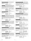
Fan Override
— This variable can be used to test the fan on se-
ries and parallel fan powered terminals. Enabling this point will
cause the terminal fan to run until this point is disabled or the
commissioning mode is ended.
Fan Override: Display Range Dsable/Enable
Default Value Dsable
Network Access Read /Write
501
→
→
→


