


25
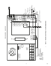
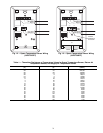
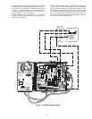
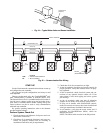
Indoor Air Quality Sensor Wiring
— To wire the sensors
after they are mounted in the conditioned air space and return
air duct, see Fig. 20 and the instructions shipped with the sen-
sors. For each sensor, use two 2-conductor 18 AWG twisted-
pair cables (unshielded) to connect the separate isolated 24 vac
power source to the sensor and to connect the sensor to the con-
trol board terminals. To connect the sensor to the control board,
identify the positive (+) PIN-8 and ground (GND) PIN-7 termi-
nals on the sensor and connect the positive terminal to terminal
RH/IAQ and connect the ground terminal to terminal GND.
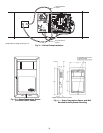
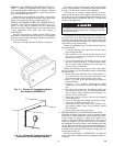
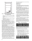
HUMIDITY SENSOR (WALL-MOUNTED) INSTALLA-
TION — The accessory space humidity sensor is installed on
an interior wall to measure the relative humidity of the air with-
in the occupied space. See Fig. 21.
The use of a standard 2- x 4-in. electrical box to accommo-
date the wiring is recommended for installation. The sensor can
be mounted directly on the wall, if acceptable by local codes.
If the sensor is installed directly on a wall surface, install the
humidity sensor using 2 screws and 2 hollow wall anchors
(field-supplied); do not overtighten screws. See Fig. 11.
The sensor must be mounted vertically on the wall. The
Carrier logo should be oriented correctly when the sensor is
properly mounted.
DO NOT mount the sensor in drafty areas such as near heat-
ing or air-conditioning ducts, open windows, fans, or over heat
sources such as baseboard heaters, radiators, or wall-mounted
light dimmers. Sensors mounted in those areas will produce in-
accurate readings.
Avoid corner locations. Allow at least 4 ft between the sen-
sor and any corner. Airflow near corners tends to be reduced,
resulting in erratic sensor readings.
Sensor should be vertically mounted approximately 5 ft up
from the floor, beside the space temperature sensor.
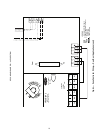
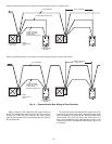
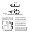
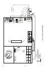
For distances up to 500 feet, use a 3-conductor, 18 or 20
AWG cable. A CCN communication cable can be used,
although the shield is not required. The shield must be removed
from the sensor end of the cable if this cable is used. See
Fig. 22 for wiring details.
The power for the sensor is provided by the control board.
The board provides 24 vdc for the sensor. No additional power
source is required.
To wire the sensor, perform the following:
1. At the sensor, remove 4-in. of jacket from the cable.
Strip
1
/
4
-in. of insulation from each conductor. Route
the cable through the wire clearance opening in the
center of the sensor. See Fig. 22.
2. Connect the RED wire to the sensor screw terminal
marked (+).
3. Install one lead from the resistor (supplied with the
sensor) and the WHITE wire, into the sensor screw ter-
minal marked (–). After tightening the screw terminal,
test the connection by pulling gently on the resistor
lead.
4. Connect the remaining lead from the resistor to the
BLACK wire and secure using a closed end type crimp
connector or wire nut.
5. Using electrical tape, insulate any exposed resistor
lead to prevent shorting.
6. At the control box, remove the jacket from the cable
and route the RED conductor over to the left side of
the control board. Route the remaining conductors to
the right side of the control board.
Do NOT clean or touch the sensing element with chemical
solvents; they can permanently damage the sensor.
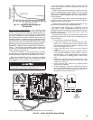
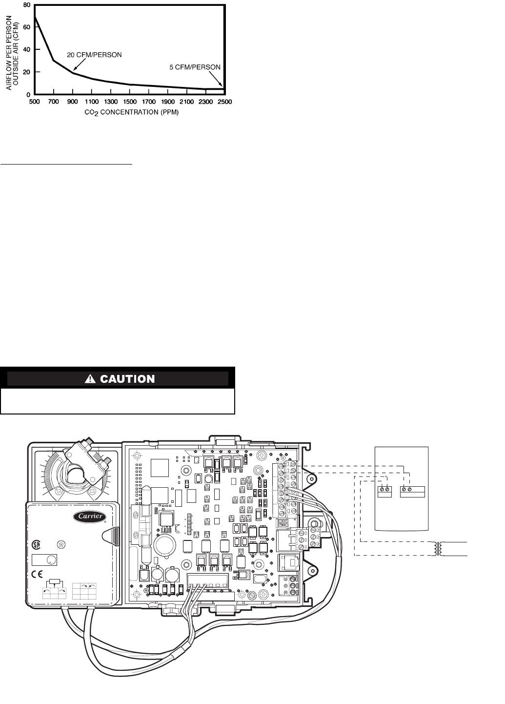
Fig. 19 — Ventilation Rated Based on
CO
2
Set Point
35 in-lb (4 Nm)
80...110s
HF23BJ042
Made in Switzerland
by Belimo Automation
1
0
yel
blu
ora
WIP
5K
LISTED
94D5
TEMP. IND. &
REG. EQUIP.
U
L
Class 2 Supply
LR 92800
NEMA 2
24VAC/DC
50/60Hz
3VA 2W
COM
1
2
3
blk
red
wht
LINE
VOLTAGE
87
21
24 VAC
RH/IAQ
GND
SEPARATE
ISOLATED
POWER
SUPPLY
REQUIRED
(24 VAC, 25 VA
MINIMUM)
*
Do not connect to the same transformer that supplies power to the zone controller.
→
Fig. 20 — Indoor Air Quality Sensor Wiring
303