


4
RELATIVE HUMIDITY SENSOR — The
33AMSENRHS000 relative humidity sensor is required for
zone humidity control (dehumidification).
NOTE: The relative humidity sensor and CO
2
sensor cannot
be used on the same zone controller.
INDOOR AIR QUALITY (CO
2
) SENSOR — An indoor air
quality sensor is required for optional demand control ventila-
tion. The CGCDXSEN002A00 CO
2
Sensor is an indoor,
wall mounted sensor with an LED display. The
CGCDXSEN003A00 CO
2
Sensor is an indoor, wall mounted
sensor without display.
NOTE: The relative humidity sensor and CO
2
sensor cannot
be used on the same zone controller.
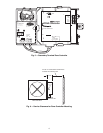
Mount Zone Controller
LOCATION — The zone controller must be mounted on the
air terminal’s damper actuator shaft. For service access, there
should be at least 12 in. of clearance between the front of the
zone controller and adjacent surfaces. Refer to Fig. 6.
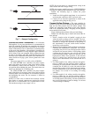
MOUNTING — Perform the following steps to mount the
zone controller:
1. Visually inspect the damper and determine the direc-
tion in which the damper shaft moves to open the
damper — clockwise (CW) or counterclockwise
(CCW). Refer to Fig. 7.
If the damper rotates CCW to open, it does not require
any configuration changes.
If the damper rotates CW to open, then the damper
actuator logic must be reversed. This is done in the
software when performing system start-up and damper
calibration test. Do not attempt to change damper rota-
tion by changing wiring. This will upset the damper
position feedback potentiometer readings.
2. Rotate the damper shaft to the fully closed position.
Note direction of rotation.
3. Press the release button on the actuator and rotate the
clamp in the same direction that was required to close
the damper in Step 2.
4. Press the release button on the actuator and rotate the
actuator back one position graduation. Release the but-
ton and lock the actuator in this position.
5. Mount the zone controller to the terminal by sliding
the damper shaft through the actuator clamp assembly.
Secure the zone controller to the duct by installing
the screw provided through the grommet in the anti-
rotation tab. Be sure the floating grommet is in the
center of the slot. Failure to center the grommet may
cause the actuator to stick or bind.
6. Tighten the actuator clamp assembly to the damper
shaft. Secure by tightening the two 10-mm nuts.
7. If the damper has less than 90 degrees of travel
between the fully open and fully closed positions, then
a mechanical stop must be set on the actuator. The
mechanical stop prevents the damper from opening
past the maximum damper position. To set the
mechanical stop, perform the following procedure:
a. Press the actuator release button and rotate the
damper to the fully open position.
b. Using a Phillips screwdriver, loosen the appropri-
ate stop clamp screw.
c. Move the stop clamp screw so that it contacts the
edge of the cam on the actuator. Secure the stop
clamp screw in this position by tightening the
screw.
8. Verify that the damper opens and closes. Press the
actuator release button and rotate the damper. Verify
that the damper does not rotate past the fully open
position. Release the button and lock the damper in the
fully open position.
HF23BJ042
Made in Switzerland
by Belimo Automation
LR 92800
NEMA 2
Class 2 Supply
LISTED
94D5
TENP IND &
REG. EQUIP.
24VAC/DC
50/60 Hz
3VA 2W
5K
WIP
yel
blu
ora
blk
red wht
COM
1
2
3
35 in-lb (4 Nm)
80...110s
0
1
J4
J3
J1
SRVC
24VAC
+
G
-
HIGH
3art Number: 33ZCFANTRM
S/N:
Bus#:
Element#:
Unit#:
J6
CCW
COM
CW
HEAT1
24VAC
HEAT2
ZONE Controller
®
®
C
US
LOW
1
6
3
1
+
G
-
J2A
CCN
LEN
J2B
+
G
-
1
1
1
3
3
2
15
16
FAN AC
FAN
24VAC
N/A
HEAT3
J7
J6
1
1
2
3
ACTUATOR
CLAMP
ASSEMBLY
DAMPER
SHAFT
LOW PRESSURE
TUBING ROUTING
GROMMET
ANTI-
ROTATION
TAB
HIGH
PRESSURE
TUBING
ROUTING
ACTUATOR
RELEASE
BUTTON
MECHANICAL
STOP
RH/IAQ
GND
SECFLOW
+10V
DMPPOS
GND
TEST
GND
+24V
SPT
GND
SAT
T56
GND
PAT
REMOTE
CW
COM
COW
J8
SEC DMP
1
3
→
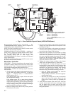
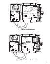
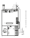
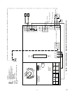
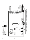
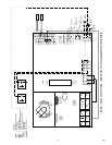
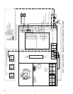
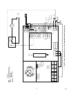
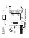
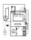
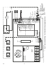
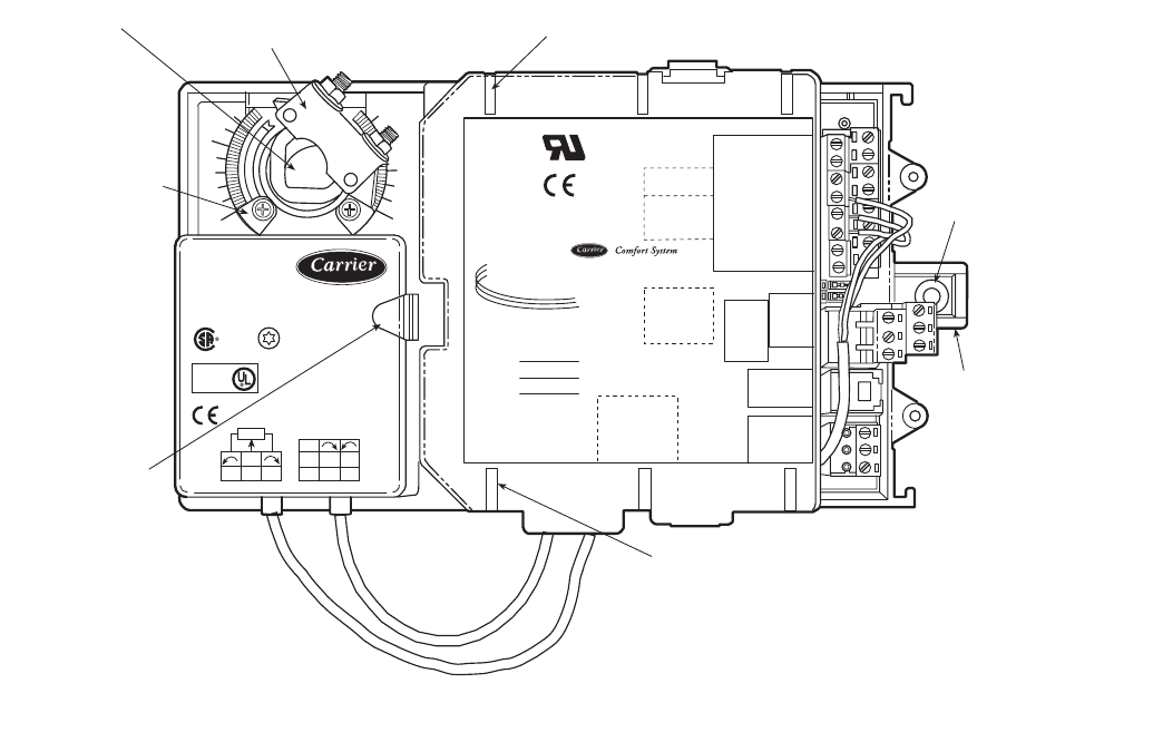
Fig. 2 — Zone Controller Physical Details (33ZCFANTRM Shown)
NOTE: Actuator clamp accepts dampers
shafts with the following characteristics:
Round —
1
/
4
-in. to
5
/
8
-in.
(6 to 16 mm)
Square —
1
/
4
-in. to
7
/
16
-in.
(6 to 11 mm)
Damper shaft must be a minimum of 1.5-in.
(38 mm) long.
801