


42
Override
— The Override parameter is used to configure the
number of hours and minutes the override will be in effect. The
user initiates override by pressing the override button on the
space temperature sensor. This will cause the schedule to enter
into the Occupied mode. If global scheduling is used, all zones
using the global schedule will enter Occupied mode. Pushing
the override button during Occupied mode will have no effect.
If the occupancy override is due to end after the start of the
next occupancy period, the mode will transition from occupan-
cy override to occupied without becoming unoccupied, and the
occupancy override timer will be reset.
NOTE: If using the tenant billing function, the override
hours set point must be configured between 1 and 3 hours.
Override: Units Hours: Minutes
Range 00:00 to 24:00
Default Value 00:00
Broadcast Acknowledger
— This configuration defines if the
zone controller will be used to acknowledge broadcast messag-
es on the CCN bus. One broadcast acknowledger is required
per bus, including secondary busses created by the use of a
bridge.
Broadcast
Acknowledger: Range No/Yes
Default Value No
Set Point Group Number
— The Set Point Group Number is
used to define the current zone controller as a part of a group of
zone controllers which share the same set points. All zone con-
trollers with the same Set Point Group Number will have the
same set points. The set points are broadcast to the group by the
zone controller defined by the Global Set Point Master config-
uration. A value of 0 is a local schedule. Values 1 to 16 are used
for global scheduling.
Set Point
Group Number: Range 0 to 16
Default Value 0
Global Set Point Master
— This configuration defines if the
current zone controller will broadcast its set point values to the
other zone controllers which are made part of the same group
by configuring the Set Point Group Number.
Global Set Point
Master: Range No/Yes
Default Value No
Maximum Offset Adjustment
— This configuration deter-
mines the maximum amount that the set point will be biased
(up or down), by adjusting the slide bar on the space tempera-
ture sensor (if installed).
Maximum Offset
Adjustment: Units delta F (delta C)
Range 0 to 15
Default Value 2
Control Options
— The Control Options configuration deter-
mines whether the zone controller will use a humidity sensor or
an indoor air quality sensor. A configuration of 0 means no
sensors are used. A configuration of 1 means a Humidity Sen-
sor is used. A configuration of 2 means an IAQ Sensor is used.
Control Options: Range 0 to 2
Default Value 0
Humidity Control
— These configuration values define the
calculation parameters for determining the airflow needed to
correct a high humidity problem in the space. The Maximum
Output Value is measured in percentage of nominal terminal
cfm.
Proportional
Gain: Range 0.0 to 9.9
Default Value 1.5
Integral Gain: Range 0.00 to 9.99
Default Value 0.30
Maximum Output
Value: Range 0.0 to 100.0% (max cool
cfm)
Default Value 100.0
Indoor Air Quality Control
— These configuration values de-
fine the calculation parameters for determining the airflow
needed to correct a high incidence of air pollution contami-
nants in the space, such as CO
2
. The Maximum Output Value is
measured in percentage of nominal terminal cfm.
Proportional Gain:Range 0.00 to 9.99
Default Value 0.10
Integral Gain: Range 0.00 to 9.99
Default Value 0.03
Maximum Output
Value: Range 0.0 to 100.0% (max cool
cfm)
Default Value 100.0
IAQ Sensor Low Voltage
— This configuration defines the
lowest voltage which should be read from the air quality
sensor.
IAQ Sensor
Low Voltage: Range 00.0 to 10.0
Default Value 0.0
IAQ Sensor High Voltage
— This configuration defines the
highest voltage which should be read from the air quality sen-
sor.
IAQ Sensor
High Voltage: Range 00.0 to 10.0
Default Value 10.0
IAQ Low Reference
— This configuration defines the value
in parts per million which correlate to the low voltage reading
from the air quality sensor.
IAQ Low
Reference: Units ppm (parts per million)
Range 0 to 5000
Default Value 0
IAQ High Reference
— This configuration defines the value
in parts per million which correlate to the high voltage reading
from the air quality sensor.
IAQ High
Reference: Units ppm (parts per million)
Range 0 to 5000
Default Value 2000
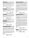
SECONDARY DAMPER SERVICE CONFIGURATION
SCREEN — The Secondary Damper Service Configuration
screen is used to configure the secondary damper settings. See
Table 12.
Zone Pressure Control
— The Zone Pressure Control config-
uration determines whether the primary and secondary control-
lers will be configured for zone pressure control.
Zone Pressure
Control: Range Dsable/Enable
Default Value Dsable
Dual Duct Type
— The Dual Duct Type setting configures the
secondary controller for the correct dual duct type. A value of 0
configures the type to None. A value of 1 configures the type to
Second Inlet (Hot Deck). A value of 2 configures the duct to
Total Probe (terminal outlet).
Dual Duct Type: Range 0 to 2
Default Value 0
800
→