


19
Install Sensors
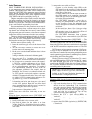
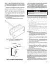
SPACE TEMPERATURE SENSOR INSTALLATION —
A space temperature sensor must be installed for each zone
controller. There are three types of SPT sensors available from
Carrier: the 33ZCT55SPT space temperature sensor with timed
override button, the 33ZCT56SPT space temperature sensor
with timed override button and set point adjustment and the
33ZCT58SPT with liquid crystal display. See Fig. 10.
The space temperature sensor is used to measure the build-
ing interior temperature and should be located on an interior
building wall. The sensor wall plate accommodates the NEMA
standard 2 x 4 junction box. The sensor can be mounted direct-
ly on the wall surface if accpectable by local codes.
Do not mount the sensor in drafty locations such as near air
conditioining or heating ducts, over heat sources such as base-
board heaters, radiators, or directly above wall mounted light-
ing dimmers. Do not mount the sensor near a window which
may be opened, near a wall corner, or a door. Sensors mounted
in these areas will have inaccurate and erratic sensor readings.
The sensor should be mounted approximately 5 ft from the
floor, in an area representing the average temperature in the
space. Allow at least 4 ft between the sensor and any corner
and mount the sensor at least 2 ft from an open doorway.
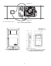
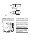
Install the sensor as follows (see Fig. 11):
1. Locate the two Allen type screws at the bottom of the
sensor.
2. Turn the two screws clockwise to release the cover
from the sensor wall mounting plate.
3. Lift the cover from the bottom and then release it from
the top fasteners.
4. Feed the wires from the electrical box through the
opening in the center of the sensor mounting plate.
5. Using two no. 6-32 x 1 mounting screws (provided
with the sensor), secure the sensor to the electrical box.
6. Use 20 gage wire to connect the sensor to the control-
ler. The wire is suitable for distances of up to 500 ft.
Use a three-conductor shielded cable for the sensor
and set point adjustment connections. The standard
CCN communication cable may be used. If the set
point adjustment (slidebar) is not required, then an
unshielded, 18 or 20 gage, two-conductor, twisted pair
cable may be used.
The CCN network service jack requires a separate,
shielded CCN communication cable. Always use sepa-
rate cables for CCN communication and sensor wir-
ing. (Refer to Fig. 12 for wire terminations.)
7. Replace the cover by inserting the cover at the top of
the mounting plate first, then swing the cover down
over the lower portion. Rotate the two Allen head
screws counterclockwise until the cover is secured to
the mounting plate and locked in position.
8. For more sensor information, see Table 1 for ther-
mistor resistance vs temperature values.
NOTE: Clean sensor with damp cloth only. Do not use
solvents.
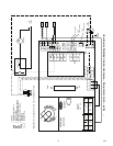
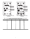
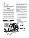
Wiring the Space Temperature Sensor
(33ZCT55SPT and
33ZCT56SPT) — To wire the sensor, perform the following
(see Fig. 12 and 13):
1. Identify which cable is for the sensor wiring.
2. Strip back the jacket from the cables for at least
3-inches. Strip
1
/
4
-in. of insulation from each conduc-
tor. Cut the shield and drain wire from the sensor end
of the cable.
3. Connect the sensor cable as follows:
a. Connect one wire from the cable (RED) to the
SPT terminal on the controller. Connect the other
end of the wire to the left terminal on the SEN ter-
minal block of the sensor.
b. Connect another wire from the cable (BLACK) to
the GND terminal on the controller. Connect the
other end of the wire to the remaining open termi-
nal on the SEN terminal block.
c. On 33ZCT56SPT thermostats, connect the re-
maining wire (WHITE/CLR) to the T56 terminal
on the controller. Connect the other end of the
wire to the right most terminal on the SET termi-
nal block.
d. In the control box, install a No. 6 ring type crimp
lug on the shield drain wire. Install this lug under
the mounting screw in the upper right corner of
the controller (just above terminal T1).
e. On 33ZCT56SPT thermostats install a jumper
between the two center terminals (right SEN and
left SET).
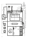
Wiring the Space Temperature Sensor (33ZCT58SPT)
— The
T58 space temperature sensor is wired differently than other
conventional sensors. The T58 sends all its sensor information
through the CCN bus to the zone controller that is is associated
with. The SPT sensor wiring connections are not used. The T58
sensor does not need to be directly wired to the zone controller.
The T58 sensor may be powered by a separate 24-VAC pow-
er supply or may be connected to the J1 24 VAC power termi-
nals on the zone controller. Be sure that the polarity of the power
supply connections are consistent. For multiple devices wired to
the same power supply, all positive (+) and negative (–) termi-
nals should be wired in the same polarity.
Wire the T58 sensor to the CCN. Connect the CCN + termi-
nal to the RED signal wire (CCN+). Connect the CCN – termi-
nal to the BLACK signal wire (CCN–). Connect the GND
terminal to the WHITE/CLEAR signal wire (Ground). Refer to
the T58 sensor Installation Instructions for more information
on installing and wiring the sensor.
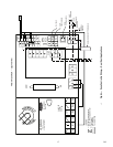
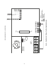
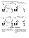
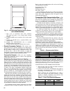
Wiring the CCN Network Communication Service Jack
—
See Fig. 12, 13, and 14. To wire the service jack, perform the
following:
1. Strip back the jacket from the CCN communication
cable(s) for at least 3 inches. Strip
1
/
4
-in. of insulation
from each conductor. Remove the shield and separate
the drain wire from the cable. Twist together all the
shield drain wires and fasten them together using an
closed end crimp lug or a wire nut. Tape off any
exposed bare wire to prevent shorting.
2. Connect the CCN + signal wire(s) (RED) to
Terminal 5.
3. Connect the CCN – signal wire(s) (BLACK) to
Terminal 2.
4. Connect the CCN GND signal wire(s) (WHITE/CLR)
to Terminal 4.
IMPORTANT: The T58 sensor must be configured with
the bus address and device type of the zone controller
before it will broadcast temperature to the zone control-
ler. Refer to the T58 sensor Installation Instructions for
more information on configuring the sensor.
→
→
801