


31
4. If the terminal is a parallel or series powered fan box,
force the Fan Override to Enable. If the damper is open
it may have to be repositioned to the proper position
depending on the box type. Damper percent change
will be displayed. After the damper is positioned cor-
rectly, the fan relay should energize and the fan should
run for a few seconds.
5. Make sure the fan runs and the Fan Override decision
returns to disabled to ensure the fan is wired correctly
for proper operation.
6. Force the Heating Override to Enable. If the unit is a
single duct unit, this must be done with the primary
terminal at reheat set point. The damper will modulate
to maintain the terminal reheat CFM. The heat outputs
will be commanded to provide maximum heat. If the
unit is a fan powered terminal, the fan must be on.
NOTE: The CFM settings can be found under service con-
figuration in the table AIRFLOW.
CONFIGURATION
The following sections describe the computer configuration
screens which are used to configure the zone controller. The
screens shown may be displayed differently when using differ-
ent Carrier software.
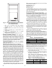
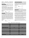
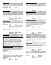
Points Display Screen —
The Points Display screen
allows the user to view the status of the air terminal controller
points. See Table 4.
TERMINAL MODE — The terminal mode is determined by
the equipment mode as reported by linkage and space require-
ments determined by space temperature and set points. The
ZEROCAL and COMMISS modes are the result of the activat-
ing the commissioning maintenance table to perform terminal
testing and commissioning.
Terminal Mode: Display Units ASCII
Default Value COOL
Display Range HEAT, COOL, VENT,
FAN AND VENT, DEHUMID, WARM-
UP, REHEAT, PRESSURE, EVAC, OFF,
ZEROCAL, COMMISS
Network Access Read only
TERMINAL TYPE — Terminal type is the confirmation of
the terminal type configuration in the SERVCONF Service
Config table.
Terminal Type: Display Units ASCII
Default value SINGLDUCT
Display Range SINGLDUCT, PAR
FAN, SER FAN, DUALDUCT
Network Access Read only
CONTROLLING SETPOINT — Controlling Setpoint will
display either the heating master reference or the cooling mas-
ter reference depending upon what mode the terminal is in. The
display will default to the heating master reference and display
the last controlling master reference when in neither heating
nor cooling.
Controlling
Setpoint Display Units F (C)
Default Value: –40
Display Range: –40 to 245
Network Access: Read only
SPACE TEMPERATURE — Space temperature from 10 kΩ
thermistor (Type III) located in the space.
Space
Temperature: Display Units F (C)
Default Value -40.0
Display Range -40.0 to 245.0
Network Access Read/Write
PRIMARY AIRFLOW — Volume of primary air calculated
for pressure reading from the velocity pressure pickup probe
located in the input collar of the air terminal.
Primary Airflow: Display Units cfm
Default Value 0
Display Range 0 to 9999
Network Access Read/Write
PRIMARY DAMPER POSITION — Damper position per-
cent range of rotation determined by the transducer calibration
procedure. The zone controller is designed be used on dampers
with any range of rotation.
Primary Damper
Position: Display Units % open
Default Value 0
Display Range 0 to 100
Network Access Read only
→
Table 4 — Points Display Screen
DESCRIPTION DEFAULT POINT NAME
Terminal Mode
COOL MODE
Terminal Type
SINGLDUCT TYPE
Controlling Setpoint
-40.0 F CNTSP
Space Temperature
-40.0 F SPT
Primary Airflow
0 cfm PRIFLO
Primary Damper Position
100 % DMPPOS
Supply Air Temperature
0.0 F SAT
Local Heating Capacity
0 % HCAP
Terminal Fan
Off FAN
Relative Humidity
0 % RH RH
Air Quality (ppm)
0 ppm AQ
Secondary Airflow
0 cfm SECFLO
Primary Air Temperature
0.0 F PATEMP
Heat
Dsable HEAT
801
→