


26
7. Strip
1
/
4
-in. of insulation from each conductor
and equip each with a
1
/
4
-in. female quick connect
terminal.
8. Connect the RED wire to terminal +24v on the control
board.
9. Connect the BLACK wire to terminal GND on the
control board.
10. Connect the WHITE/CLEAR wire to terminal
RH/IAQ on the control board.
11. Connect shield to ground (if shielded wire is used).
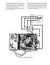
Remote Occupancy Contact —
The remote occu-
pancy input (J4 pin 2) has the capability to be connected to a
normally open or normally closed occupancy dry contact. Wire
the dry contact as show in Fig. 23 between J4 Pin 2 and
24 VAC J1 Pin 1. The 24 VAC necessary to supply the
ComfortID™ Controller remote occupancy contact input shall
be supplied using the existing ComfortID Controller.
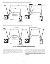
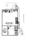
Connect the Outputs —
Wire the zone controller’s
outputs (fan, staged heat, valves) as shown in the applicable
wiring diagrams in Fig. 8A-J.
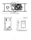
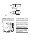
Modulating Baseboard Hydronic Heating —
In-
stall the water valve on the leaving water end of the baseboad
heater. See Fig. 24. Observe the fluid flow direction when
mounting the valve. Be sure to properly heat sink the valve and
direct the flame away from the actuator and valve body when
sweating the valve connections. Install the leaving water tem-
perature sensor (33ZCSENCHG) on the hydronic heating coil
as shown. The sensor accommodates nominal copper pipe
from
1
/
2
to 1-in. (OD sizes from
5
/
8
to 1.125 in.). It should be
secured to the pipe with the clamp supplied. If piping is larger
than 1-in. nominal size, a field-supplied clamp must be used.
Use fiberglass pipe insulation to insulate the sensor assembly.
Refer to Fig. 8C and 8H to wire the modulating water valve
and the sensor to the zone controller. Connect the leaving water
temperature sensor to the controller using the wiring connec-
tions shown for the SAT sensor. (NOTE: The leaving water
temperature sensor replaces the SAT sensor in this application.)
Use 18 or 20 AWG wire for all connections. The water valve
actuator housing may be used as a junction box if the leaving
water temperature sensor cable is not long enough and the sen-
sor cable must be extended to reach the controller.
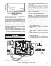
For modulating hydronic heating applications, the default
configuration must be changed to properly control the valve.
Refer to the service configuration table and set the Heating
Loop parameters as follows:
Proportional Gain = 20.0
Integral Gain = 0.5
Derivative Gain = 0.0
Start Value = 102.0
Also, set the Ducted Heat decision to YES and set the Max-
imum Duct Temperature decision equal to the design (maxi-
mum) boiler water temperature minus 20 degrees, but not
greater than 200 degrees F.
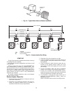
Connect the CCN Communication Bus —
The
zone controllers connect to the bus in a daisy chain arrange-
ment. The zone controller may be installed on a primary CCN
bus or on a secondary bus from the primary CCN bus. Con-
necting to a secondary bus is recommended.
At 9,600 baud, the number of controllers is limited to 128
zones maximum, with a limit of 8 systems (Linkage Coordina-
tor configured for at least 2 zones). Bus length may not exceed
4000-ft, with no more than 60 devices on any 1000-ft section.
Optically isolated RS-485 repeaters are required every 1000 ft.
At 19,200 and 38,400 baud, the number of controllers
is limited to 128 maximum, with no limit on the number of
Linkage Coordinators. Bus length may not exceed 1000 ft.
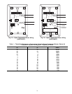
The first zone controller in a network connects directly to
the bridge and the others are wired sequentially in a daisy chain
fashion. Refer to Fig. 25 for an illustration of CCN Communi-
cation Bus wiring.
The CCN Communication Bus also connects to the zone
controller space temperature sensor. Refer to the Install the
Sensors section for sensor wiring instructions.
COMMUNICATION BUS WIRE SPECIFICATIONS —
The Carrier Comfort Network (CCN) Communication Bus
wiring is field-supplied and field-installed. It consists of
shielded three-conductor cable with drain (ground) wire. The
cable selected must be identical to the CCN Communication
Bus wire used for the entire network. See Table 2 for recom-
mended cable.
Table 2 — Recommended Cables
NOTE: Conductors and drain wire must be at least 20 AWG
(American Wire Gage), stranded, and tinned copper. Individual con-
ductors must be insulated with PVC, PVC/nylon, vinyl, teflon, or
polyethylene. An aluminum/polyester 100% foil shield and an outer
jacket of PVC, PVC/nylon, chrome vinyl, or Teflon with a minimum
operating temperature range of –20
°
C to 60
°
C is required.
CONNECTION TO THE COMMUNICATION BUS
1. Strip the ends of the red, white, and black conductors
of the communication bus cable.
2. Connect one end of the communication bus cable to
the bridge communication port labeled COMM2 (if
connecting on a secondary bus).
When connecting the communication bus cable, a
color code system for the entire network is recom-
mended to simplify installation and checkout. See
Table 3 for the recommended color code.
Table 3 — Color Code Recommendations
MANUFACTURER CABLE PART NO.
Alpha
2413 or 5463
American
A22503
Belden
8772
Columbia
02525
SIGNAL TYPE
CCN BUS WIRE
COLOR
PLUG PIN
NUMBER
+
Red 1
Ground
White 2
–
Black 3
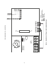
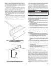
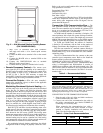
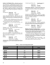
Fig. 21 — Wall Mounted Relative Humidity Sensor
(P/N 33AMSENRHS000)
801
→