


8
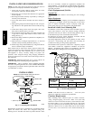
Compressor Operation on 24ANA1 Models
The basic scroll design has been modified with the addition of an
internal unloading mechanism that opens a by --pass port in the first
compression pocket, effectively reducing the displacement of the
scroll. The opening and closing of the by --pass port is controlled
by an internal electrically operated solenoid. The modulated scroll
uses a single step of unloading to go from full capacity to
approximately 67% capacity.
A single speed, high efficiency motor continues to run while the
scroll modulates between the two capacity steps. Modulation is
achieved by venting a portion of the gas in the first suction pocket
back to the low side of the compressor, thereby reducing the
effective displacement of the compressor.
Full capacity is achieved by blocking t hese vents, thus increasing
the displacement to 100%. A DC solenoid in the compressor
controlled by a rectified 24 volt AC signal in the external solenoid
plug moves the slider ring that covers and uncovers these vents.
The vent covers are arranged in such a manner that the compressor
operates at approximately 67% capacity when the solenoid is not
energized and 100% capacity when the solenoid is energized. The
loading and unloading of the two step scroll is done ”on the fly”
without shutting off the motor between steps.
NOTE: 67% compressor capacity translates to approximately
75% cooling capacity at the indoor coil.
The compressor will always start unloaded and stay unloaded for
five seconds even when the thermostat is calling for high--stage
capacity.
Crankcase Heater Operation
The crankcase heater is energized during unit off cycle regardless
of OAT temperature on 24ANA7 models.
The crankcase heater is energized during off cycle below
65_F/18.33_C on 24ANA1 models.
Outdoor Fan Motor Operation
The outdoor unit control energizes the outdoor fan any time the
compressor is operating except for low--ambient cooling operation.
The outdoor fan remains energized if a pressure switch or
compressor overload should open. Outdoor fan motor will
continue to operate for one minute after the compressor shuts off
when the outdoor ambient is greater than or equal to
100_F/37.78_C to allow for easier starting during next cooling
cycle.
On 24ANA7 models, the outdoor fan remains energized during the
1--minute compressor staging time delay.
On 24ANA7 models, the outdoor fan motor is a PSC type. A fan
relay on the control board turns the fan off and on by opening and
closing a high voltage circuit to the motor. It does not change
speeds between low-- and high--stage operation.
On 24ANA1 models, the outdoor fan is an ECM type. The motor
control is continuously powered with high voltage. The motor
speed is determined by electrical pulses provided by the PWM
outputs on the control board. The ECM motor RPM adjusts to
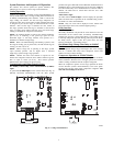
outdoor conditions as described in Table 3. The PWM output can
be measured between the PWM1 and PWM2 terminals on the
circuit board with a volt meter set to DC volts.
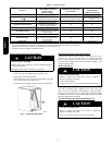
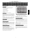
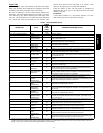
Table 3 – Outdoor Fan Motor PWM
Outdoor Temp (DC volts, Tolerance +/-- 2%)
MODEL
LOW ---STAGE
(OAT≤104_F/40_C)
HIGH ---STAGE
(OAT≤104_F/40_C)
LOW --- & HIGH ---
STAGE
(OAT>104_F/40_C)
24ANA124 9.57 10.88 11.90
24ANA136 9.06 10.23 11.90
24ANA148 9.91 11.04 11.90
24ANA160 10.83 11.70 11.90
NOTE:
For 24ANA1 models in low---ambient cooling, the PWM output for both
high --- and low ---stage equals the value for low ---stage operation below 55_F
(12.8_C).
In low ambient cooling (below 55_F/12.78_C) on 24ANA7 and
24ANA1 models, the control board cycles the fan off and on.
Time Delays
The unit time delays include:
S Five minute time delay to start cooling or heating operation
when there is a call from the thermostat or user interface. To
bypass this feature, momentarily short and release Forced
Defrost pins.
S Five minute compressor re--cycle delay on return from a
brown--out condition.
S Two minute time delay to return to standby operation from last
valid communication (with Infinity only).
S One minute time delay of outdoor fan at termination of cooling
mode when outdoor ambient is greater than or equal to
100_F/37.78_C.
S On 24ANA7 models there is a 1 minute time delay between
staging from low to high and from high to low capacity. On
24ANA1 models there is no d elay; the compressor will change
from low to high and from high to l ow capacity on the fly to
meet the demand.
Low Ambient Cooling
If this unit will be required to operate below 55_F/12.78_C
outdoor temperature, provisions must be made for low ambient
operation.
Infinity Controlled low ambient cooling:
This unit is capable of low ambient cooling down to
0_F/--17.78_C without a kit ONLY when using Infinity control. A
low ambient kit is not required, and the outdoor fan motor does not
need to be replaced for I nfinity controlled low ambient operation.
The Infinity Control provides an automatic evaporator coil freeze
protection algorithm that eliminates the need for an evaporator
freeze thermostat. Low ambient cooling must be enabled in the
User Interface set up. Fan may not begin to cycle until about
40_F/4.4_C OAT. Fan will cycle based on coil and outdoor air
temperature.
Infinity controlled low ambient mode operates as follows:
S FanisOFF whenoutdoorcoiltemp is< (outdoorair temperature+
3 _F/1.67_C) or outdoor fan has been ON for 30 minutes. (Fan is
turned off to allow r efrigerant system to stabilize.)
S Fan is ON when outdoor coil temp > (outdoor air temperature +
25_F/13.89_C)oroutdoorcoiltemp>80_F/26.67_Corifoutdoor
fan has been OFF for 30 minutes. (Fan is turned on to allow
refrigerant system to stabilize.)
S Low pressure switch is ignored for first 3 minutes during low
ambient start up. After 3 minutes, if LPS trips, then outdoor fan
motoristurned offfor10 minutes,withthecompressorrunning. If
LPS closes within 10 minutes then cooling continues with the
outdoor fan cycling per the coil temperature routine listed above
for the remainder of the cooling cycle. If the LPS does not close
within 10 minutes, then the normal LPS trip response (shut down
cooling operation and generate LPS trip error) will occur.
For 24ANA1 models, the PWM output for both high-- and
low--stage equals the value for low--stage operation below 55_F
(12.8_C).
24ANA