


6
Make Airflow Selections
Airflow Setup for Infinity Control Furnace of FE Fan
coil
(communicating)
When using an Infinity User Interface, airflow is
automatically selected based on equipment size. See User
Interface Installation Instructions for available
adjustments.
Airflow Selection for Variable Speed Furnaces
for
Models Using N on--Communicating
(non--Infinity)
Thermostats
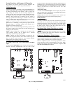
The variable speed furnaces provide blower operation to match the
capacities of the compressor during high and low stage cooling
operation, The furnace control board allows the installing
technician to select the proper a irflows for each stage of cooling.
Below is a summary of required adjustments. See furnace
installation instructions for more details:
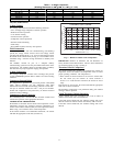
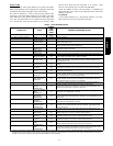
1. Turn SW1 --5 ON for 400 CFM/ton airflow or OFF for 350
CFM/ton airflow. Factory default is OFF.
2. The A/C DIP switch setting determines airflow during high
stage cooling operation. Select the A/C DIP switch setting
corresponding to the available airflow shown in the furnace
installation instructions that most closely matches the re-
quired airflow shown in the air conditioning Product Data
for HIGH speed.
3. The CF DIP switch setting determines airflow during low
stage cooling operation. Select the CF DIP switch setting
corresponding to the available airflow shown in the furnace
installation instructions that most closely matches the re-
quired airflow shown in the air conditioning Product Data
for LOW speed.
If a higher or lower Continuous Fan speed is desired, the
Continuous Fan speed can be changed using the fan switch on the
thermostat. Refer to the furnace installation instructions for details
of how to use this feature.
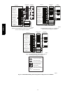
Airflow Selection for FV4 Fan Coils for Models Using
Non--Communicating (non--Infinity)
Thermostats
The FV4B provides high-- and low--stage blower operation to
match the capacities of 24ANA7 compressor at high-- and
low--stage. The FV4C provides high-- and low--stage blower
operation t o match the capacities of 24ANA1 compressor at high--
and low--stage (units containing circuit board HK38EA015 or
newer). To select recommended airflow , refer to the FV4
Installation Instructions. The FV4 utilizes an Easy Select control
board that allows the installing technician to select proper airflows.
For adjustments to control board and recommended A/C SIZE and
CFM ADJUST selections. This fan coil has an adjustable blower
off delay factory set at 90 sec. for high-- and low--stage blower
operation.
For other combinations of equipment consult the Product Data
Sheet.
START--UP
CAUTION
!
UNIT OPERATION AND SAFETY HAZARD
Failure to follow this caution may result in minor personal
injury, equipment damage or improper operation.
To prevent compressor damage or personal injury,
observe the following:
S Do not overcharge system with refrigerant.
S Do not operate unit in a vacuum or at negative pressure.
S Do not disable low pressure switch
S Dome tem peratures may be hot in scroll and bottom
temperatures may be hot in recip.
CAUTION
!
ENVIRONMENTAL HAZARD
Failure to follow this caution may result in environmental
damage.
Federal regulations require that you do not vent
refrigerant to the atmosphere. Recover during system
repair or final unit disposal.
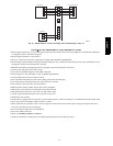
Follow these steps to properly start up the system:
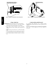
1. After system is evacuated, fully back seat (open) liquid and
vapor service valves.
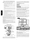
2. Unit is shipped with valve stem(s) front seated (closed) and
caps installed. Replace stem caps after system is opened to
refrigerant flow (back seated). Replace caps finger--tight and
tighten with wrench an additional 1/12 turn.
3. Close electrical disconnects to energize system.
4. Set room thermostat or User Interface at desired temperat-
ure. Be sure set point is below indoor ambient temperature
and is set low enough to energize desired stage.
5. Set room thermostat or User Interface to COOL and fan
control to ON or AUTO mode, as desired. Operate unit for
15 minutes. Check system refrigerant charge.
NOTE: Non--communicating (non--Infinity) Carrier electronic
thermostats are equipped with a 15--minute staging timer. This
timer prevents the 2--stage system from operating at high--stage
until unit has been operating in low--stage for 15 minutes unless
there is at least a ±5_F(±2.78_C) difference between room
temperature and thermostat set point. To force high--stage (after a
minimum of 2 minutes in low --stage), adjust the set point at least
±5_ (±2.78_C) below room ambient.
6. Set room thermostat to COOL and fan control to AUTO or
ON as desired. Wait for appropriate time delay(s). Operate
unit for 15 minutes. Check refrigerant charge.
24ANA