


5
Refrigerant tubes and indoor coil should be evacuated using the
recommended deep vacuum method of 500 microns. The alternate
triple evacuation method may be used. See Service Manual for
triple evacuation method. Always break a vacuum with dry
nitrogen._
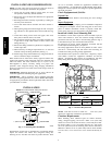
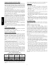
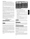
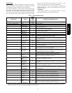
Deep Vacuum Method
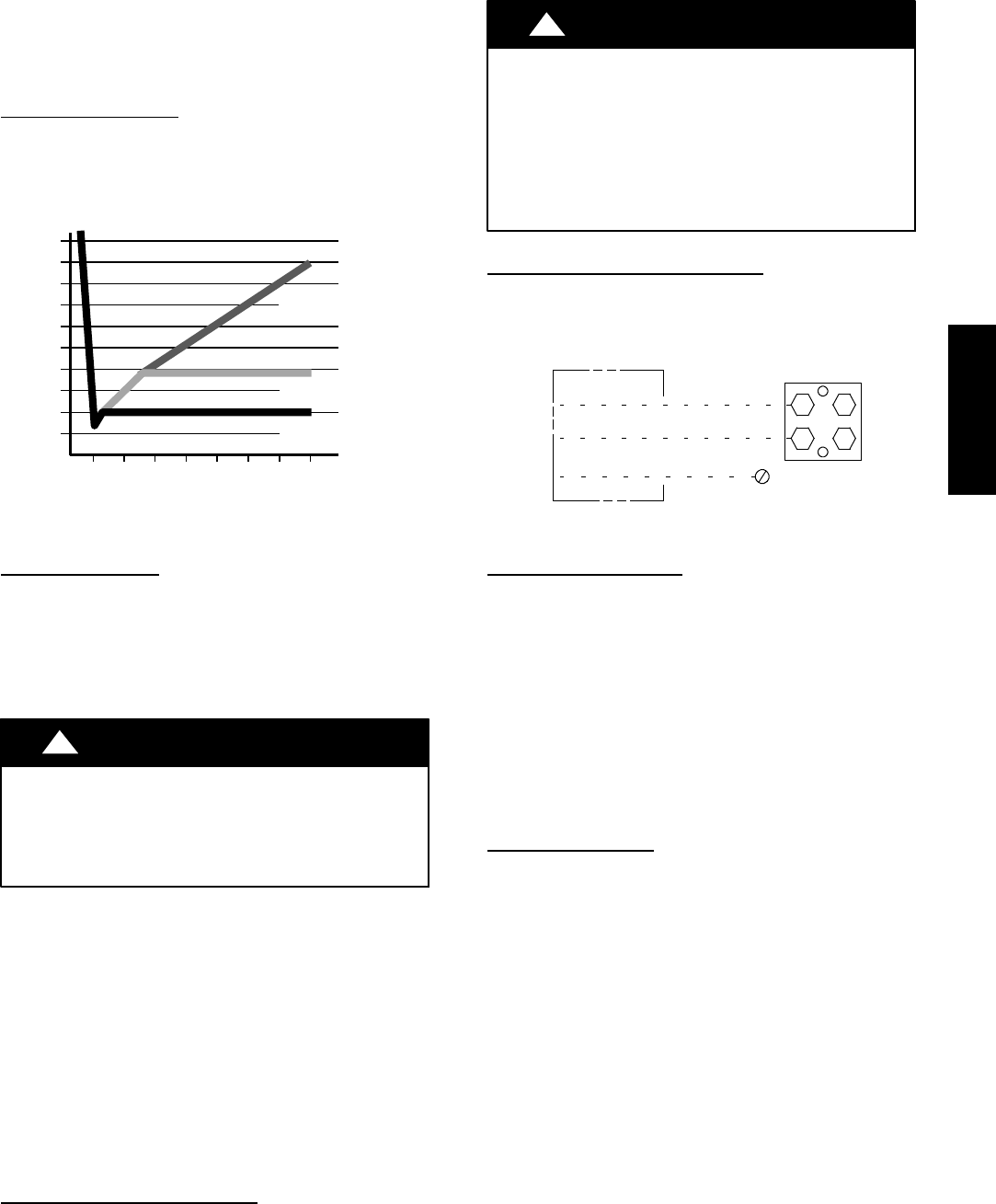
The deep vacuum method requires a vacuum pump capable of
pulling a vacuum of 500 microns and a vacuum gage capable of
accurately measuring this vacuum depth. The deep vacuum method
is the most positive way of assuring a system is free of air and
liquid water. ( See Fig. 4)
500
MINUTES
01234567
1000
1500
LEAK IN
SYSTEM
VACUUM TIGHT
TOO WET
TIGHT
DRY SYSTEM
2000
MICRONS
2500
3000
3500
4000
4500
5000
A95424
A95424
Fig. 4 -- Deep Vacuum Graph
Final Tubing Check
IMPORTANT: Check to be certain factory tubing on both indoor
and outdoor unit has not shifted during shipment. Ensure tubes are
not rubbing against each other or any sheet metal. Pay close
attention to feeder tubes, making sure wire ties on feeder tubes are
secure and tight.
Make Electrical Connections
!
WARNING
ELECTRICAL SHOCK HAZARD
Failure to follow this warning could result in personal
injury or death.
Do not supply power to unit with compressor terminal
box cover removed.
Be sure field wiring complies with local and national fire, safety,
and e lectrical codes, and voltage to system is within limits shown
on unit rating plate. Contact local power company f or correction of
improper voltage. See unit rating plate for recommended circuit
protection device.
NOTE: Operation of unit on improper line voltage constitutes
abuse and could affect unit reliability. See unit rating plate. Do not
install unit in system where voltage may fluctuate above or below
permissible limits.
NOTE: Use copper wire only between disconnect switch and unit.
NOTE: Install branch circuit disconnect of adequate size per NEC
to handle unit starting current. Locate disconnect within sight from
and readily accessible from unit, per Section 440--14 of NEC.
Route Ground and Power Wires
Remove access panel to gain access to unit wiring. Extend wires
from disconnect through power wiring hole provided and into unit
control box.
!
WARNING
ELECTRICAL SHOCK HAZARD
Failure to follow this warning could result in personal
injury or death.
The unit cabinet must have an uninterrupted or unbroken
ground to minimize personal injury if an electrical fault
should occur. The ground may consist of electrical wire or
metal conduit when installed in accordance with existing
electrical codes.
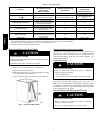
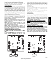
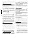
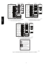
Connect Ground and Power Wires
Connect ground wire to ground connection in control box for
safety. Connect power wiring to contactor as shown in Fig. 5.
DISCONNECT
PER N. E. C.AND/OR
LOCAL CODES
CONTACTOR
GROUND LUG
FIELD GROUND
WIRING
FIELD POWER
WIRING
A91056
Fig. 5 -- Line Power Connections
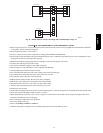
Connect Control Wiring
Route low--voltage control wires through control wiring grommet
and connect leads to control board.
For Infinity, connect to ABCD only. For standard
non--communicating thermostats, connect to standard thermostat
connections R, C, Y1 and Y2.
Use No. 18 AWG color-- coded, insulated (35_C minimum) wire
for all installations.
All wiring must be NEC Class 1 and must be separated from
incoming power leads.
Use furnace transformer or fan coil transformer for control power,
24--v/40--va minimum. The outdoor unit requires a minimum of
27va/24 vac control power.
Final Wiring Checks
IMPORTANT: Check factory wiring and field wire connections
to ensure terminations are secured properly . Check wire routing to
ensure wires are not in contact with tubing, sheet metal, etc.
CompressorCrankcaseHeater
Furnish power to crankcase heater a minimum of 24 hr before
starting unit. To furnish power to heater only, set thermostat to
OFF and close electrical disconnect to outdoor unit.
NOTE: On 24ANA7 models, starting the compressor without a
minimum of 12 hours of crankcase heat prior to initial start--up
may result in a compressor chattering noise and possible damage to
the compressor.
Install Accessories
Refer to the individual instructions packaged with kits or
accessories when installing.
24ANA