


4
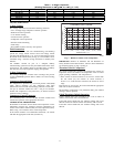
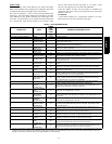
Table 2 – Accessory Usage
Accessory
REQUIRED FOR
LO W --- AMB IENT C OO LI NG
APPLICATIONS
(Below 55°F/12.8_C)
REQUIRED FOR LONG LINE
APPLICATIONS*
REQUIRED FOR SEA COAST
APPLICATIONS
(Within 2 miles/3.22 km)
Accumulator No No No
Compressor Start Assist Capacitor and
Relay}
Standard on 24ANA7 models.
Not required for 24ANA1 models.
Standard on 24ANA7 models.
Not required for 24ANA1 models.
Standard on 24ANA7 models.
Not required for 24ANA1
models.
Crankcase Heater Standard Standard Standard
Evaporator Freeze Protection
Standard with Infinity Control
(Low Ambient not allowed with non---
communicating Thermostat)
No No
Liquid Line Solenoid Valve No No No
Low---ambient Control
Standard with Infinity Control (Low Am-
bient not allowed with non---communi-
cating thermostat)
No No
Puron Balance Port Hard Shut---off TXV
Yes{
Yes{ Yes{
Winter Start Control
Standard with Infinity Control (Low Am-
bient not allowed with Non---Commu ni-
cating Thermostat)
No No
Support Feet Recommended No Recommended
* For Tubing Set lengths between 80 an d 200 ft. (24.38 and 60.96 m) horizontal or 20 ft. (6.10 m) vertical differential (250 ft./76.2 m Total Equivalent Length),
refer to the Residential Piping and Long Line Guideline for Air Conditioners and Heat Pumps using Puron® Refrigerant.
{ Required on all indoor units. Standard on all new Puron fan coils and furnace coils.
} Infor mation is specific to 24ANA7 and 24ANA1 models.
Install Liquid--Line Filter Drier Indoor
CAUTION
!
UNIT DAMAGE HAZARD
Failure to follow this caution may result in equipment damage
or improper operation.
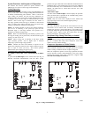
Installation of filter drier in liquid line is required.
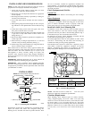
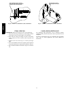
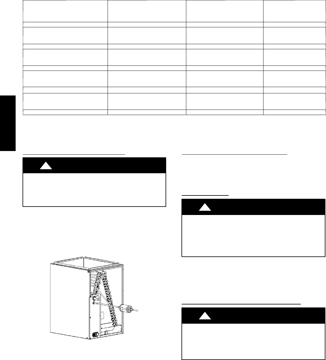
Refer to Fig. 3 and install filter drier as follows:
1. Braze 5 in. (127 mm) liquid tube to the indoor coil.
2. Wrap filter drier with damp cloth.
3. Braze filter drier to a bove 5 in. (127 mm) liquid tube. Flow
arrow must point towards indoor coil.
4. Connect and braze liquid refrigerant tube to the f ilter drier.
A05178
Fig. 3 -- Liquid Line Filter Drier
Refrigerant Tubing Connection Outdoor
Connect vapor tube to fitting on outdoor unit vapor service valves
(see Table 1.) Connect and braze the 3/8 in. coupling (provided
with the filter drier) to the liquid service valve and connect and
braze the liquid tubing to the other end of this coupling. Use
refrigerant grade tubing.
Sweat Connection
CAUTION
!
UNIT DAMAGE HAZARD
Failure to follow this caution may result in equipment
damage or improper operation.
S Use a brazing shield
S Wrap service valves with wet cloth or heat sink material.
Use refrigerant grade tubing. Service valves are closed from factory
and ready for brazing. After wrapping service valve with a wet
cloth, braze sweat connections using industry accepted methods
and materials. Consult local code requirements. Refrigerant tubing
and indoor coil are now ready for leak testing. This check should
include all field and factory joints.
Evacuate Refrigerant Tubing and Indoor Coil
CAUTION
!
UNIT DAMAGE HAZARD
Failure to follow this caution may result in equipment
damage or improper operation.
Never use the system compressor as a vacuum pump.
24ANA