


7
System Functions And Sequence Of Operation
The outdoor unit control system h as special functions. The
following is an overview of the 2--stage control functions:
Cooling Operation
24ANA7 and 24ANA1 (containing circuit board HK38EA015 or
newer) models utilize e ither a 2--stage cooling indoor thermostat or
an Infinity communicating User Interface. With a call for first
stage cooling, the outdoor fan and low--stage compressor are
energized. If low--stage cannot satisfy cooling demand, high--stage
is energized by the second stage of indoor thermostat or User
Interface. After second stage is satisfied, the unit returns to
low--stage operation until first stage is satisfied or until second
stage is required again. When both first stage and second stage
cooling are satisfied, the compressor will shut off.
NOTE: On 24ANA7 models, if unit h as not operated within the
past 12 hrs, or following a unit power--up, upon the next
thermostat high -- or low--stage demand, unit operates for a
minimum of 5 minutes in high--stage.
NOTE: With non--communicating (non--Infinity) systems, with
first stage of cooling, (Y1) is powered on; and with second stage of
cooling, (Y1 and Y2) are on.
NOTE: When 2--stage unit is operating at low--stage, system
vapor (suction) pressure will be higher than a standard
single--stage system or high--stage operation.
NOTE: Outdoor fan motor will continue to operate for one
minute after compressor shuts off, when outdoor ambient is greater
than or equal to 100_F (37.78_C). This reduces pressure
differential for easier starting on the next cycle.
Communication and Status Function Lights
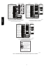
For Infinity Contr ol Only, Green communications (COMM)
Light
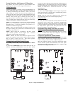
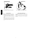
A green LED (COMM light) on the outdoor board (see Fig. 6)
indicates successful communication with the other system
products. The green LED will remain OFF until communications is
established. Once a valid command is received, the green LED will
turn ON continuously. If no communication is received within 2
minutes, the LED w ill be turned OFF until the next valid
communication.
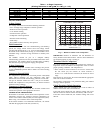
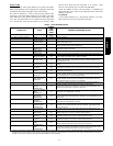
Amber Status Light
An amber colored STATUS light is used to display the operation
mode and fault codes as specified in the troubleshooting section.
See Table 6 for codes and definitions.
NOTE: Only one code will be displayed on the outdoor unit
control board (the most recent, with the highest priority).
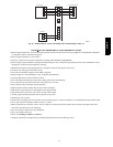
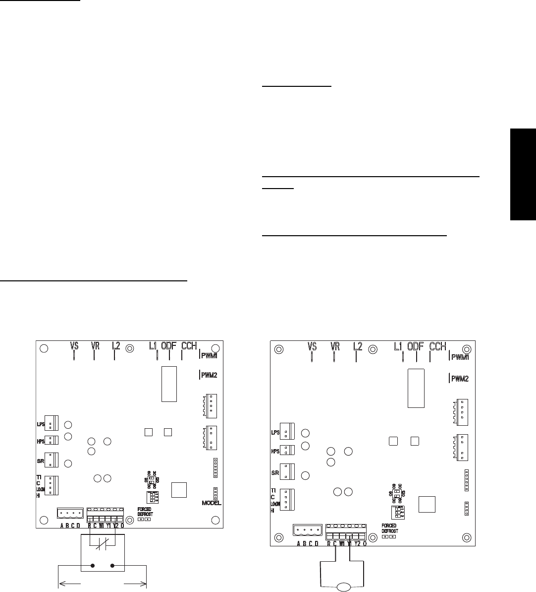
Utility Interface
With Infinity Control
The utility curtailment relay should be wired between R and Y2
connections on the control board for Infinity Communicating
Systems only (see Fig. 6.) This input allows a power utility device
to interrupt compressor operation during peak load periods. When
the utility sends a signal to shut the system down, the User
Interface will display, “Curtailment Active”.
One Minute Stage Change Time Delay on 24ANA7
Models
When compressor changes stages from high to low or low to high,
there is a 1--minute time delay before compressor restarts. The
outdoor fan motor remains running.
Compressor Operation on 24ANA7 Models
When the compressor operates in high--stage operation, the motor
rotates clockwise. Both the lower and upper pistons are eccentric
with the rotating crankshaft and both compress refrigerant.
When the compressor operates in low--stage operation the motor
reverses direction (rotates counterclockwise). The lower piston
becomes idle and the upper piston compresses refrigerant. The
start and run windings are reversed.
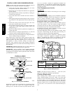
UTILITY RELAY
*
UTILITY SIGNAL
OPEN RELAY
* SUPPLIED BY UTILITY PROVIDER
LLS
Liquid Line Solenoid
MODEL
PLUG
A06526
Fig. 6 -- 2-- Stage Control Board
24ANA