


13
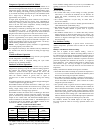
Status Codes
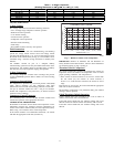
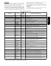
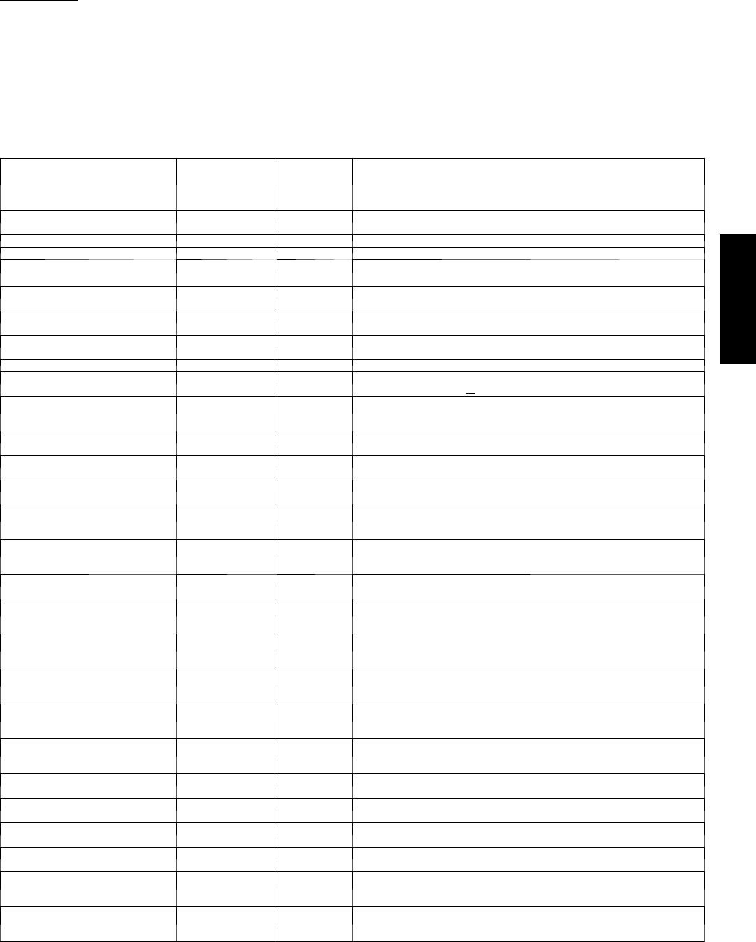
Table 6 shows the status codes flashed by the amber status light.
Most system problems can be diagnosed by reading the status code
as flashed by the amber status light on the control board.
The codes are flashed by a series of short and long flashes of the
status light. The short flashes indicate t he first digit in the status
code, followed by long flashes indicating the second digit of the
error code. The short flash is 0.25 seconds ON and the long flash
is 1.0 second ON. Time between flashes is 0.25 seconds. Time
between short flash and first long flash is 1.0 second. Time
between code repeating is 2.5 seconds with LED OFF.
Count the number of short and long flashes to determine the
appropriate flash code. Table 6 gives possible causes and actions
related to each error .
EXAMPLE:
3 short flashes followed by 2 long flashes indicates a 32 code.
Table 6 shows this to be low pressure switch open.
Table 6 – TROUBLESHOOTING
OPERATION
FAUL T
AMBER
LED
FLASH
CODE
POSSIBLE CAUSE AND ACTION
Standby – no call for unit operation None
On solid, no
flash
Normal operation
low---stage Cool/Heat Operation None 1, pause Normal operation
high---stage Cool/Heat Operation None 2, pause Normal operation
System Commu-
nications Failure
16 Communication with user interface lost. Check wiring to User Interface,
indoor and outdoor units
Invalid Model Plug 25
Control does not detect a model plug or detects an invalid model plug. Unit
will not operate without correct model plug.
High Pressure
Switch Open
31*
High---pressure switch trip. Check refrigerant charge, outdoor fan operation
and coils for airflow restrictions.
Low Pressure
Switch Open
32* Low pressure switch trip. Check refrigerant charge and indoor air flow
Control Fault 45 Outdoor unit control board has failed. Control bo ard needs to be replaced.
Brown Out (230 v) 46
Line voltage < 187v for at least 4 seconds. Compressor and fan operation
not allowed until voltage>
190v. Verify line voltage.
No 230v at Unit 47
There is no 230v at the contactor when indoor unit is powered and cooling/
heating demand exists. Verify the disconn ect is closed and 230v wiring is
connected to the unit.
Outdoor Air Temp
Sensor Fault
53
Outdoor air sensor not reading or out of ran ge. Ohm out sensor and check
wiring.
Outdoor Coil Sen-
sor Fault
55 Coil sensor not reading or out of range. Ohm out sensor and check wiring.
Thermistors out of
range
56
Improper rela tionship between coil sensor and outdoor air sensor. Ohm out
sensorsand check wiring.
low ---stage Ther-
mal Cutout
71*
Compressor o peration detected then disappears while low---stage demand
exists. Possible causes are internal compressor overload trip or start relay
and capacitor held in circuit too long(if installed)
high---stage Ther-
mal Cutout
72*
Compressor o peration detected then disappears while high---stage demand
exists. Possible causes are internal compressor overload trip or start relay
and capacitor held in circuit too long (if installed)
Contactor Shorted 73
Compressor voltage se nsed when no demand for compressor operation
exists. Contactor m ay be stuck closed or th ere is a wiring error.
No 230V at Com-
pressor
(24ANA1 Only)
74
Compressor voltage not sensed when compressor should be starting. Con-
tactor may be stuck open or there is a wiring error.
low ---stage Did Not
Start
(24ANA7 Only)
75
Specified start voltage at VR terminal was not achieved in low---stage. Start
relay was de---energized after 1 second.
low ---stage Did Not
Start 3 times
(24ANA7Only)
76
For 3 consecutive low---stage starts, the specified start voltage at VR terminal
was not achieved & start rela y was de---energized. low---stage locked out for
30 minutes.
high ---stage Did
Not Start
(24ANA7 Only)
77
Specified start voltage at VS t erminal w as not achieved in high---stage. Start
relay was de---energized after 1 second.
high ---stage Did
Not Start 3 times
(24ANA7 Only)
78
For 3 consecutive hi g h---stage starts, the specified start voltage at VS termi-
nal was not achieved & start relay was de---energized. high---stage locked
out for 30 minutes.
low ---stage Ther-
mal Lockout
81
Thermal cutout occurs in t hree consecutive low/ high---stage cycles. low---
stage locked out for 4 hours or until 24v power recycled.
high---stage Ther-
mal Lockout
82
Thermal cutout occurs in three consecutive high/low---stage cycles. high---
stage locked out for 4 hours or until 24v power recycled.
Low Pressure
Lockout
83
Low pressure switch trip has occurred during 3 c onsecutive c ycles. Unit
operation locked out for 4 hours or until 24v power recycled.
High Pressure
Lockout
84
High p ressure switch trip has occurred during 3 c onsecutive c ycles. Unit
operation locked out for 4 hours or until 24v power recycled.
Low Contactor
Open
(24ANA7 Only)
85
Compressor voltage not sensed when compressor should be starting. low---
stage contactor may be stuck open or there is a wiring error.
High Contactor
Open
(24ANA7 Only)
87
Compressor voltage not sensed when compressor should be starting. high---
stage contactor may be stuck open or there is a wiring error.
* Sequence: Compressor contactor is de---energized and outdoor fan is energized for up to 15 minu tes. If demand still exists, control will energize compressor
contactor after 15 minute delay. If fault is cleared, unit will resume operation. If fault still exists, fan shuts off, and error code continues to flash. Control will
attempt re---start every 15 minutes. Cycling low voltage defeats the 15 minute delay.
24ANA