


10
The control is shipped with the brownout active. The change in
status is remembered until toggled to a new status. A power
down/power up sequence will not reset the status. It may be
necessary to do the toggle twice to cycle to the desired state of the
defeat.
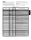
230V Line (Power Disconnect) Detection
If there is no 230v at the compressor contactor(s) when the indoor
unit is powered and cooling demand exists, the appropriate error
code is displayed (see Table 6). Verify that the disconnect is closed
and 230v wiring is connected to the unit.
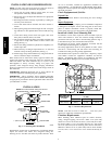
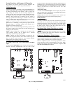
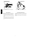
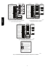
Compressor Voltage Sensing
The control board input terminals labeled VS, VR and L2 on
24ANA7 models and VS and L2 on 24ANA1 models (see Fig. 6)
are used to detect compressor voltage status, and alert the user of
potential problems. The control continuously monitors the high
voltage on the run capacitor of the compressor motor. Voltage
should be present any time the compressor contactor is energized,
and voltage should not be present when the contactor is
de--energized.
Contactor Shorted Detection
If there i s compressor voltage sensed when there is no demand for
compressor operation, the contactor may be stuck closed or there is
a wiring error. The control will flash the appropriate fault code.
24ANA7 Models, Compressor Thermal Cutout
The control senses the compressor voltage at VR and VS. When
starting or running, a phase difference of the voltages on the inputs
will indicate the thermal protector is closed. If the phase difference
is 5 degrees or less for 10 seconds, the internal protector is open.
The control de-- energizes the appropriate compressor contactor for
15 minutes, but continues to operate the outdoor fan. The control
Status LED will flash the appropriate code shown in Table 6. After
15 minutes, with a call for low-- or high--stage cooling, the
appropriate compressor contactor is energized. If the thermal
protector has not re-- set, the outdoor fan is turned off. If the call for
cooling or heating continues, the control will energize the
compressor contactor every 15 minutes. If the thermal protector
closes, (at the next 15 minute i nterval check), the unit will resume
operation.
If the thermal cutout trips for three consecutive cycles, then unit
operation is locked out for 4 hours and the appropriate fault code is
displayed.
24ANA1 Models, Compressor Thermal Cutout
If the control senses the compressor voltage after start--up, and is
then absent for 10 consecutive seconds while cooling demand
exists, the thermal protector is open. The control de--energizes the
compressor contactor for 15 minutes, but continues to operate the
outdoor fan. The control Status LED will flash the appropriate
code shown in Table 6. After 15 minutes, with a call for low -- or
high--stage cooling, the compressor contactor is energized. If the
thermal protector has not re--set, the outdoor fan is turned off. If
the call for cooling continues, the control will energize the
compressor contactor every 15 minutes. If the thermal protector
closes, (at the next 15 minute i nterval check), the unit will resume
operation.
If the thermal cutout trips for three consecutive cycles, then unit
operation is locked out for 4 hours and the appropriate fault code is
displayed.
Low or High Contactor Open (24ANA7 models) / No
230V at Compressor (24ANA1
models)
If the compressor voltage is not sensed when the compressor
should be starting, the appropriate contactor may be stuck open or
there is a wiring error. The control will flash the appropriate fault
code. Check the contactor and control box wiring.
24ANA7 Models Only, Compressor S tart Detection
In low--stage, if t he specified start voltage at VR terminal is not
achieved, the start relay is de--energized after 1 second and the
control will flash the appropriate fault code.
In high--stage, if the specified start voltage at VS terminal is not
achieved, the start relay is de--energized after 1 second and the
control will flash the appropriate fault code.
If the specified start voltage is not achieved for 3 consecutive
low--stage starts, low--stage operation is locked out for 30 minutes.
If the specified start voltage is not achieved for 3 consecutive
high--stage starts, high--stage operation is locked out for 30
minutes. The control will flash the appropriate fault code.
Tr oubleshooting 24ANA7 units for proper switching
between low-- &
high--stages
Check the suction and liquid pressures at the service valves.
Suction pressure should be reduced by 5--10% when switching
from low to high capacity. There should be a 10--20% increase in
liquid pressure when switching from low to high capacity.
Compressor current should increase 100 --250% when switching
from low to high--stage.
Tr oubleshooting 24ANA1 units for proper switching
between low-- &
high--stages
Check the suction pressures a t the service valves. Suction pressure
should be reduced by 3 --10% when switching from low to high
capacity.
NOTE: The liquid pressures are very similar between low-- and
high--stage operation, so liquid pressure should not be used for
troubleshooting.
Compressor current should increase 20--45% when switching from
low-- to high--stage. The compressor solenoid when energized in
high--stage, should measure 24vac.
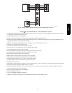
When the compressor is operating in low--stage the 24v DC
compressor solenoid coil is de--energized. When the compressor is
operating in high--stage, the 24v DC solenoid coil is energized.
The solenoid plug harness that is connected to the compressor has
an internal rectifier that converts the 24v AC signal to 24v DC.
DO NOT INSTALL A PLUG WITHOUT AN INTERNAL
RECTIFIER.
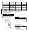
Unloader Test Procedure
The unloader is the compressor internal mechanism, controlled by
the DC solenoid, that modulates between high -- and low-- stage. If
it is suspected that the unloader is not working, the following
methods may be used to verify operation.
1. Operate the system and measure compressor amperage.
Cycle the unloader on and off at 30 second plus intervals at
the UI (from low-- to high--stage and back to low--stage).
Wait 5 seconds after staging to high before taking a reading.
The compressor amperage should go up or down at least 20
percent.
2. If step one does not give the expected results, remove the
solenoid plug from the compressor and with the unit run-
ning and the UI calling for high--stage, test the voltage out-
put at the plug with a DC voltmeter. The reading should be
24 volts DC.
3. If the correct DC voltage is at the control circuit molded
plug, measure the compressor unloader coil resistance. The
resistance should be 32 to 60 ohms depending on com-
pressor temperature. If the coil resistance is infinite, much
lower than 32 ohms, or is grounded, the compressor must
be replaced.
24ANA