


40
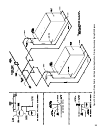
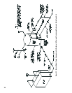
N. CONNECT TANKLESS HEATER PIPING as
shown in Figure 37a. See Table IV for Tankless Heater
Ratings.
NOTICE
The following guidelines should be followed when
piping the tankless heater:
1. Install Flow Regulator
If ow through the heater is greater than its rating,
the supply of adequate hot water may not be able to
keep up with the demand. For this reason a FLOW
REGULATOR matching the heater rating should be
installed in the cold water line to the heater. Refer
to Figure 37a for piping recommendations. Locate
the ow regulator below the inlet (cold water side)
of the heater and a minimum of 36” away from the
inlet so that the regulator is not subjected to excess
temperatures during “off” periods when it is possible
for heat to be conducted back through the supply
line. The ow regulator will limit the ow of supply
water regardless of inlet pressure variations ranging
from 20 to 125 psi.
2. Install Water Temperature Mixing Valve
WARNING
Install a mixing valve at the tankless heater
outlet to avoid risk of burns or scalding due to
excessively hot water at xtures. Do not operate
the boiler when equipped with a tankless heater
unless mixing valve is operating properly.
Refer to Figure 37a for piping recommendations.
Adjust and maintain the mixing valve in accordance
with manufacturers instructions.
Installation of a mixing valve will also lengthen the
delivery of the available hot water by mixing some
cold water with the hot. In addition, savings of hot
water will be achieved since the user will not waste
as much hot water while seeking desired water
temperature. Higher temperature hot water required
by dishwashers and automatic washers is possible
by piping the hot water from the heater prior to
entering the mixing valve. An electric hot water
booster can also be used. The mixing valve should
be “trapped” by installing it below the cold water
inlet to heater to prevent lime formation in the valve.
3. Flushing of Heater
All water contains some sediment which settles
on the inside of the coil. Consequently, the heater
should be periodically backwashed. This is
accomplished by installing hose bibs as illustrated
in Figure 37a and allowing water at city pressure to
run into hose bib A, through the heater, and out hose
bib B until the discharge is clear. The tees in which
the hose bibs are located should be the same size as
heater connections to minimize pressure drop.
4. Hard Water
A water analysis is necessary to determine the
hardness of your potable water. This is applicable
to some city water and particularly to well water.
An appropriate water softener should be installed
based on the analysis and dealer’s recommendation.
This is not only benecial to the tankless heater but
to piping and xtures plus the many other benets
derived from soft water.
CAUTION
Do not operate tankless heater with hard water.
Tankless failure will result. Install water softener
if hard water is present.
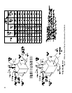
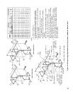
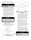
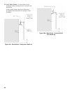
Figure 34: Mounting Elevations of M&M 150 and 63
Float Low Water Cut-Offs
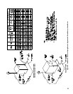
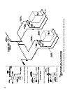
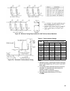
Figure 35: Recommended Piping for Combination
Heating & Cooling (Refrigeration) Systems
Water Boilers