


29
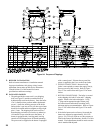
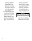
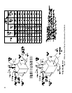
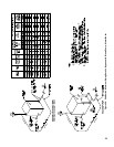
Boiler
Model
Number
of
Sections
Length
A
Width
B*
Height
C**
Approx.
Center of
Gravity
D***
Approx.
Shipping
Weight
LBS***
V903A 3 63-5/8 34-1/2 61 17-1/2 1478
V904A 4 69-5/8 34-1/2 61 20-1/2 1790
V905A 5 75-5/8 34-1/2 61 23-1/2 2102
V906A 6 81-5/8 34-1/2 61 27-1/2 2418
V907A 7 87-5/8 34-1/2 61 30-1/2 2734
V908A 8 93-5/8 34-1/2 61 33-1/2 3071
V909A 9 105-5/8 34-1/2 61 37-1/2 3452
V910A 10 111-5/8 34-1/2 61 40-1/2 3809
V911A 11 117-5/8 34-1/2 61 43-1/2 4120
V912A 12 123-5/8 34-1/2 61 46-1/2 4447
* Width can vary with gas train conguration.
If the V9A packaged boiler must pass through a 36” doorway, please
specify.
** Add 6-1/2” to dimension C when equipped with optional top outlet.
*** Varies slightly with burner and gas train conguration and with or without RTC.
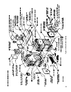
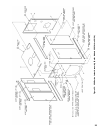
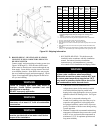
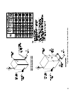
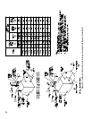
1. Do not tilt. Exercise caution when lifting to avoid damage.
2. This boiler can be lifted by fork truck. Do not truck from front.
3. When lifting from rear, forks must extend beyond center of gravity and second skid
cross bar.
4. When lifting from side, forks must extend to opposite skid rail and straddle center
of gravity.
5. Cable spreader is to prevent jacket damage. Spreader width should equal B (width
of skid) + 12”. Adjust cable lengths to lift at approximate center of gravity per chart.
Figure 25: Shipping Information
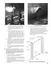
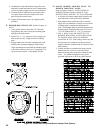
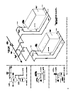
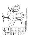
L. BOILER PIPING - HEATING APPLICATIONS
CONNECT SUPPLY AND RETURN PIPING TO
HEATING SYSTEM
Connect supply and return piping to heating system (see
Figures 26 through 32). Flow direction for hot water
boilers must be from the rear return out through the top
front supply. Steam boilers can pipe return to the front
as an alternate location. Some boiler sizes may require
the use of additional supply and return tappings. Check
Figure 24 and applicable piping diagram for the boiler
size you are installing.
WARNING
Failure to properly pipe boiler may result in
improper, unsafe system operation and void
manufacturer’s warranty.
DO NOT improperly pipe boiler.
WARNING
All steam and hot water pipes must have
clearances of at least 1/2” from all combustible
construction.
WARNING
A hot water boiler installed above radiation level
must be provided with a low water cutoff device
as part of the installation.
1. HOT WATER HEATING - This boiler must be
installed in strict accordance with this installation
manual Deviations from these installation
instructions may void manufacturer’s warranty.
Also consult I=B=R Installation and Piping Guides.
WARNING
Continued boiler operation for prolonged periods
of time under conditions when temperature
differential across the system exceeds 40°F and/
or, return water temperature stays below 135°F,
may result in premature boiler failure due to ue
gas condensation and/or thermal shock.
a. If the boiler is used in connection with
refrigeration systems, boiler must be installed
with chilled medium piped in parallel with
heating boiler using appropriate valves to prevent
chilled medium from entering boiler. See Figure
35.
b. If the boiler is connected to heating coils
located in air handling units where they may be
exposed to refrigerated air, boiler piping must
be equipped with ow control valves to prevent
gravity circulation of boiler water during cooling
system operation.
c. Burnham Commercial recommends maintaining
temperature differential (drop) across the system
at 40°F or less, and return water temperature at
minimum of 135°F for optimum operation and
long-term reliability.