


23
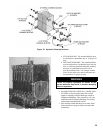
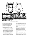
Figure 17: Left Side Canopy Intermediate Bracket
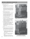
Figure 18: Right Side Canopy
Intermediate Bracket
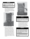
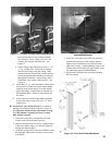
on center section draw-up rod (hooks should
face outward). Secure canopy with 5/16” at
washers, lock washers and brass nuts. See
Figure 17.
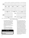
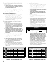
d. Secure canopy right side bracket(s) with ¼ - 20
x 5” lg. carriage bolts. Insert head of carriage
bolt between canopy body and casting. Slide
carriage bolt into slot provided between castings.
Lower carriage bolt until threaded end will pass
through hole in bracket. Secure canopy with ¼”
at washers, lock washers and brass nuts. See
Figure 18.
13. Attach the 1/8” x 1” wide self-adhesive ber gasket
to the surfaces of either the top ue outlet damper
assembly or top outlet canopy cover that mounts
against the canopy. Gasket must be centered over
all attachment holes. Do not overlap corners, cut
butt joints.
14. Secure either the top ue outlet damper assembly
or top outlet canopy cover with #10 x 1/2” sheet
metal screws.
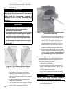
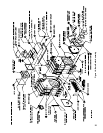
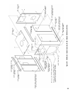
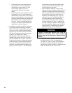
B. INSTALL FLUE COVER PLATES over cleanout
openings on left side of boiler as shown in Figure 19.
See Important Product Safety Information on Page
21 of this manual, regarding refractory ceramic
ber product warning.
1. Locate the cover plates, carriage bolts, nuts and
washers in the boiler assembly carton(s).
2. Remove insulation from two (2) 3/8” diameter holes
in ue cover plates using a 3/8” drill bit. Rotate bit
through insulation by hand.
3. Attach the carriage bolts to the top and bottom of the
ue openings with washers and hex nuts to provide
a xed stud.
4. Install ue cover plates over studs with insulation
against boiler and secure with washers and nuts.
Tighten until insulation on cover plate provides a
tight seal to casting. If after tightening, a gap is still
evident where the sections join, apply silastic along
top and bottom edge of insulation board.
5. Repeat steps 3 through 6 for mounting remaining
ue cover plates.
Figure 19: Flue Cover Plate Attachment