


12
WARNING
When a V9A gas red boiler is connected
to a venting system that is designed so that
it will operate under a positive pressure,
manufactured vent systems, designed and
approved for positive pressure application per
UL1738, must be used (for example, Van-Packer
model CS, Protech Model FasNSeal / FasNSeal
W2, Heatfab Saf-T-Vent or equivalent).
When a V9A oil red or combination gas/oil
red boiler is connected to a venting system
that is designed so that it will operate un-
der a positive pressure, manufactured vent
systems, designed and approved for posi-
tive pressure application, must be used (for
example, Selkirk Metalbestos Model PS / IPS,
Van-Packer Model ES or equivalent).
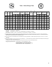
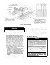
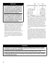
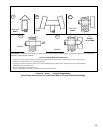
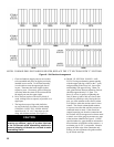
The V9A Series boiler is designed for forced draft
ring and may be used with a conventional natural draft
stack (15’ minimum height) or a stub vent, sometimes
called a diesel stack (see Figure 3a). See Table I for
the proper vent outlet size. For low silhouette vent
terminations, see Figure 3b. Draft controls are not
normally required, although they may be used on
installations where a natural draft stack is used or on
multiple boiler installations with a common stack. The
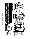
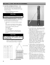
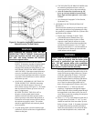
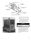
boiler is provided with a breeching damper, which
should be adjusted to maintain a positive pressure of
0.1” W.C. in the vent connector box during burner high
re operation (see breeching pressure sensing port in
Figure 1).
If the venting system is designed for positive or forced
draft venting, the boiler, vent connector and stack will
operate under positive pressure. Gas tight vent systems
designed for pressure systems must be used to prevent
ue by-product leakage. The vent height is usually
limited to prevent negative draft, typically three (3)
feet above the roof line (see Figure 3a). The damper
shall be adjusted to maintain a positive pressure of
0.1” W.C. in the vent connector box during burner high
re operation (see breeching pressure sensing port in
Figure 1).
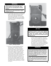
If the venting system is designed for negative pressure
(natural draft), the boiler still operates with positive
pressure in the chamber and up to the xed damper on
the ue collar. However, if the venting system is larger
than what is required, the stack will provide a surplus
draft (or negative pressure) that may require the use of
a barometric damper to maintain the positive 0.1” W.C.
pressure at the ue outlet. Multiple forced draft boiler
stacks should always be designed as negative to ensure
the products of combustion do not exit a boiler that is
not ring.
WARNING
Venting instructions are recommendations only. Consult a venting expert on the design of a specic
vent system for your application. The ASHRAE Venting Guide and The National Fuel Gas Code, NFPA
54 should be considered in all venting systems.
Conventional vent material may not be suitable for the application. Flue gases can leak carbon
monoxide from the joints on these materials and can result in severe personal injury or death.
Installations having long horizontal runs or an excessive amount of tees or elbows will restrict the ow
of combustion gases and can result in condensation, ue gas leakage of carbon monoxide, resulting in
severe personal injury or death.
Figure 3a: Typical Arrangement for Stub Vent