


20
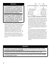
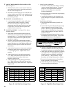
SECTION III - INSTALLATION INSTRUCTIONS
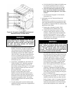
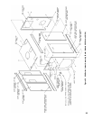
A. INSTALL CANOPY/FLUE OUTLET ASSEMBLY,
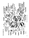
Refer to Figures 14, 15 and 16.
1. Open canopy carton.
2. Attach the two (2) canopy brackets to the front end
cap of canopy with four (4) #10 x 1/2” sheet metal
screws each.
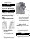
3. Across the top of the front section and along the top
ledges running back each side of the sections, place
continuous 2” wide strips of cerafelt and overlap
joints at front corners. Cerafelt strip should extend
1/4” beyond rear surface of back section. Cut off
excess.
4. Place the canopy on the sections.
5. Position rear ange (end with studs) of canopy ush
with rear surface of back section.
6. Loosely attach the canopy brackets to the lugs on
the front section of the block assembly with 5/16”
carriage bolts, at washers and locknuts.
7. Check to see if rear ange of canopy is still ush
with raised ange on back section.
8. Open either the rear ue outlet carton (standard) or
top ue outlet carton (optional).
9. Attach the 1/8” x 1” wide self-adhesive ber gasket
to the surface of either the rear ue outlet damper
assembly or rear ue outlet cover that mounts
against the canopy and back section. Gasket must
be centered over all attachment holes. Do not
overlap corners, cut butt joints.
10. Attach either the rear ue outlet damper assembly
or rear outlet canopy cover to the canopy with the
5/16” at wasters, lock-washers and brass
nuts and tighten securely. Attach the rear ue
outlet damper assembly or cover to the back section
with the four (4) 5/16” at washers and cap screws
and tighten securely.
11. Tighten front canopy carriage bolt until canopy is
secure.
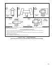
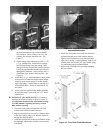
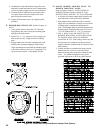
12. On the longer canopy sizes, Intermediate Mounting
Brackets are provided, two (2) are required on sizes
V907A thru V909A and four (4) are required on
sizes V910A thru V912A. Refer to Figures 17 and
18.
a. Intermediate brackets are shipped at. Bend
side anges down approximately 90° as shown.
Adjust bends until holes in bracket match hole
pattern on canopy.
b. Secure brackets to both sides of canopy with
three (3) #10 x ½” sheet metal screws per
bracket.
c. Secure canopy left side bracket(s) with
appropriate canopy ‘J’ bolt(s). Insert threaded
end through holes in brackets and hook ‘J’ bolt
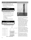
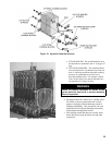
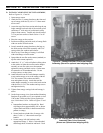
Figure 14: Canopy with Rear Flue Outlet Damper
Assembly (Shown on optional steel shipping skid)
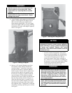
Figure 15: Canopy with Top Flue Outlet Damper
Assembly (Rear Cover Removed)
(Shown on optional steel shipping skid)