


14
SECTION II - CAST IRON BLOCK ASSEMBLY
A. FACTORY ASSEMBLED SECTIONS — If the
boiler was ordered with factory assembled sections,
the assembly should be set in the proper location as
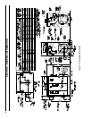
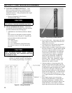
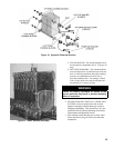
outlined in Section I. Lifting arrangement and weights
are given in Figure 4.
1. Proceed to Paragraph C of this Section,
“HYDROSTATIC TEST”.
CAUTION
Boiler sections must be drawn-up on perfectly
level surface or improper assembly may result.
B. FIELD ASSEMBLED SECTIONS — If the boiler
was ordered to be eld assembled, follow the assembly
procedure outlined on the following pages.
1. ASSEMBLY OF SECTIONS (MANUAL DRAW-
UP)
These sections are designed to be drawn together,
one section at a time, using the 9¾” long draw-up
rods (provided) and ordinary hand tools.
Tools required:
(1) ¾” Drive Ratchet
(1) 1-1/16” Socket
(1) 1-1/16” Combination or Open End Wrench
(1) Container of grease, oil or other appropriate
lubricant.
CAUTION
When assembling sections without hydraulic
draw-up equipment, never assemble more than
one section at a time.
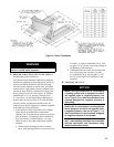
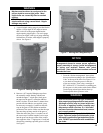
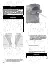
a. Place the rear section in its approximate nal
position, as outlined in Section I, and support it
with a suitable prop and wedges. See Figure 5.
Figure 5: Positioning of Back Section
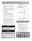
Figure 4: Lifting Instruction
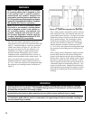
b. On size V903A only— Open target wall carton,
apply Silastic to back of target wall and secure
target wall to rear section.
c. Clean the groove in the ground joint along the
edge of the section with the wire brush.
d. Open the Boiler Assembly Carton(s) and remove
the bottle of adhesive. Using the dauber supplied
in the bottle, apply the adhesive to the groove.
Be sure to use enough adhesive to sufciently
coat the entire groove surface. If so desired,
a multi-purpose spray adhesive (supplied by
others) may be used instead. HOWEVER,
GREAT CARE MUST BE TAKEN TO
ENSURE THAT THE ADHESIVE DOES
NOT COME IN CONTACT WITH THE
NIPPLES OR NIPPLE PORTS.
e. While the adhesive is becoming tacky, clean
nipples and nipple ports thoroughly with a de-
greasing solvent. Use the Loctite #592 provided
to lubricate the nipples and nipple ports. Apply
the lubricant to the nipples and nipple ports,
then use a brush to disperse it evenly around the
nipples and the nipple ports. Use approximately
25 ml of Loctite #592 per ueway [(1) 7” and
(2) 3” nipples and their (6) corresponding nipple
ports].
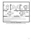
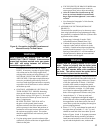
f. Drive nipples squarely into section using
block of wood and hammer, or preferably, an
aluminum head hammer. (Burnham offers a
Polyethylene Block for setting the nipples, part
number 8052601). Place block over entire
nipple edge and hit the wood with the hammer.