


18
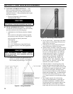
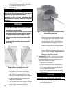
draw-up rod clamps on the other. These items
are all located in the Draw-Up Kit.
See Figure 12.
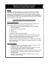
CAUTION
Do not apply pressure directly on threaded
tappings on front and rear sections with draw-up
channels during assembly procedures.
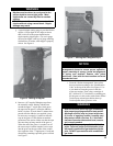
Rods should be approximately centered in
openings so that rods and couplings (when
used) do not drag on pipe thread in end section
tappings.
WARNING
READ THE STATEMENTS BELOW BEFORE
ATTEMPTING TO USE HYDRAULIC EQUIPMENT.
• Release pressure in ram pumps before
attempting to remove clamps.
• Do not stand in line with draw-up rods at either
end when hydraulic pressure is being applied.
As a safety measure, ends of draw-up rods
should be covered while sections are being
drawn in case rods should snap while under
tension.
• Do not operate ram against draw-up coupling.
• Do not operate pump after ram has reached
stroke limit.
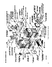
e. Draw-Up Sections
Use hydraulic rams to draw up sections by
applying pressure alternately on the draw-up
rods. When rams reach stroke limit, release
pressure in ram pumps and then move clamps to
new position.
f. Continue to draw-up until all sections make
contact at the ground joints.
g. After all sections have been drawn up, but before
removing the hydraulic rams and draw-up rods,
the 9¾” long tie rods must be installed.
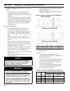
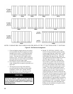
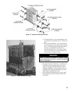
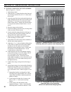
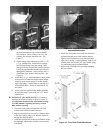
Figure 10: Front and Rear Section Channel
Block Positions (Hydraulic Draw-Up)
Figure 11: Center Section Channel Block Position
(Partial Block Draw-Up)
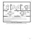
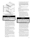
The large draw-up rod lugs with dual holes cast
in the four (4) corners of each casting. Starting
with the upper holes in the back section, install
four (4) 5/8” x 9¾” long tie rods along with
washers and nuts. Continue installing the tie
rods alternating from the upper to lower set
of holes in draw-up lugs until front section is
secured. Be certain that all sections are drawn
up IRON TO IRON at all three nipple ports.
h. Excess length of draw-up rods must not extend
beyond front and rear section to ensure proper t
of jacket, adjust accordingly. Tighten all tie rod
nuts until nger tight. Then tighten them an
additional ½ turn with a wrench.
C. HYDROSTATIC TEST — After the boiler sections
have been assembled, it is essential that the boiler be
hydrostatically tested before the canopy, ue cover
plates, jacket, or piping is installed.
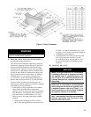
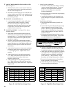
1. Tankless Heater Installation
If boiler is ordered with tankless heaters, install
heaters with the gaskets provided. Table IV gives
the maximum number of heaters permissible per
assembly and the heater ratings.
2. Plug all boiler tappings and ll boiler completely
with cold water.
CAUTION
DO NOT install gauge until after hydrostatic
testing the boiler. Gauge failure may result.
3. All completed boilers must satisfactorily pass the
prescribed hydrostatic test.