


43
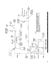
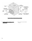
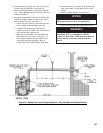
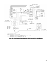
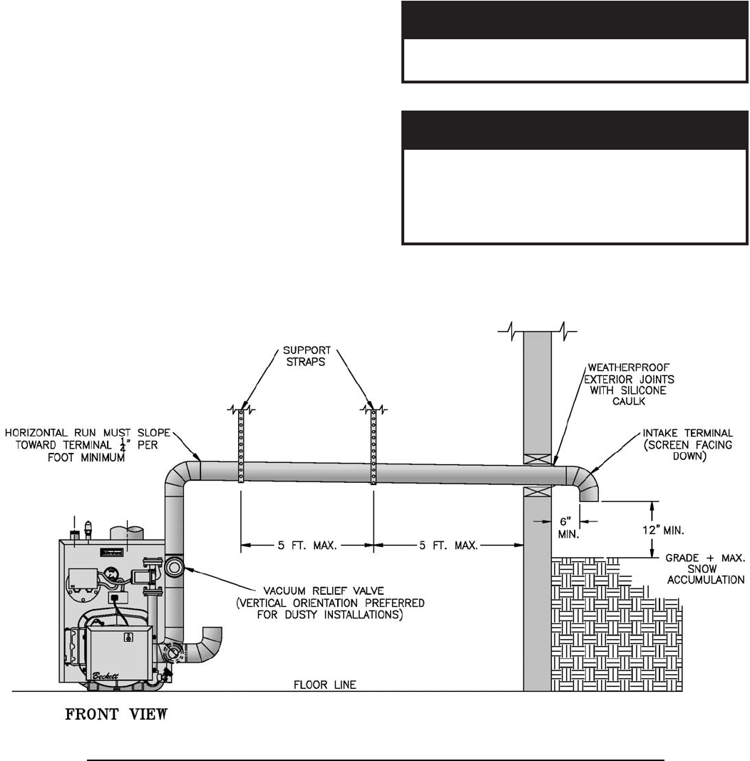
Figure 18: Optional Air Intake Piping Installation - Only Available with Beckett Burner
2. After determining location, cut a hole in the wall to
accept 4 inch air intake pipe. See Figure 18.
3. Remove the metal knockout in right side of burner
cover. Install Burnham Inlet Air Accessory Kit, Part
Number 611280031.
4. Mount the Vacuum Relief Valve Tee Assembly (Part
Number 8116268 included with Kit) or 90° elbow
into the burner inlet ring. See Figure 18.
a. Secure with at least three (3) sheet metal screws
evenly spaced around the burner inlet ring.
b. Assemble the vacuum relief valve balance
weight onto the gate. Refer to the vacuum relief
valve manufacturer's instructions.
c. Mount the vacuum relief valve into the tee and
fasten with a screw and nut in collar tabs. To
ensure proper operation, the gate must be level
across the pivot point and plumb. Refer to
vacuum relief valve manufacturer's instructions.
5. Install remainder of air intake, securing each joint
with at least three (3) sheet metal screws evenly
spaced.
6. Install air intake terminal. See Figure 18.
ECITON
sehcni21tsaeltaebtsumlanimretekatnI
.noitalumuccawonssulpedargevoba
7. Seal all external joints with weatherproof caulk.
GNINRAW
muelorteperehwekatniriaetacoltonoD
elitalov,stnegreted,s'CFC,setallitsid
.tneserperaslacimehcrehtoynarosropav
lliweruliafdnanoisorrocreliobereveS
.tluser