24
Q. INSTALL TRIM AND CONTROLS WITH
CARLIN ELITE EZ BURNER.
Follow instructions in Paragraph N, Steps 1 through 7.
Steam Boilers Only (see Figures 1D and 5).
8. Connect Field Wiring
a. Steam Boiler with Hydrolevel CG450 LWCO,
Carlin Burner.
Connect the fi eld wiring to the pressure limit, the
LWCO, R8239C Control Center and the burner
disconnect J-box or directly to burner J-box on
burners less disconnect harness (power cord).
If equipped with tankless heater, connect fi eld
wiring from the aquastat control to the R8239C
Control Center’s “R-G” terminals. Make the
wiring connections as shown in Figure 19.
b. Steam Boiler with McDonnell & Miller
PS-801 or McDonnell & Miller 67 LWCO,
Carlin Burner.
Connect the fi eld wiring to the pressure limit,
the R8239C Control Center, the LWCO and
the burner disconnect J-box. If equipped with
tankless heater, connect fi eld wiring from
the aquastat control to the oil burner primary
control’s “T-T” Terminals. Make the wiring
connections as shown in Figures 20 and 21.
c. Refer to Paragraph S for details on use of burner
disconnect junction box provided with all
knockdown boiler builds.
Water boilers Only (see Figures 1A, 1B, 1C and 5).
Follow instructions in Paragraph O, Steps 1 through 7.
9. Connect Field Wiring
a. Water boilers without tankless heater and with
front tankless heater. Connect the fi eld wiring
from the circulator to the aquastat control and
from the control to the burner disconnect J-box
or directly to oil burner primary control on
burners less disconnect harness (power cord).
Make the wiring connections as shown on
Figures 22 and 23A.
b. Water boilers with rear tankless heater. Connect
the fi eld wiring from a standard junction box
or burner disconnect J-box to the circulator,
aquastat control and burner. Make the wiring
connections as shown on Figure 23B.
c. Refer to Paragraph S for details on use of burner
disconnect junction box provided with all
knockdown boiler builds.
R. INSTALL TRIM AND CONTROLS WITH
RIELLO BURNER.
Follow instructions in Paragraph N, Steps 1 through 7.
Steam Boilers Only (see Figures 1D and 5).
8. Connect Field Wiring
a. Steam boiler with Hydrolevel CG450 or
McDonnell & Miller 67 LWCO, Riello Burner.
Connect the fi eld wiring to the pressure limit,
the LWCO, R8239C Control Center and the
burner disconnect J-box or directly to oil burner
primary control on burners less disconnect
harness (power cord). If equipped with tankless
heater, connect fi eld wiring from the aquastat
control to the R8239C Control Center’s “R-G”
terminals. Make the wiring connections as shown
in Figures 19 and 21.
b. Steam boiler with McDonnell & Miller PS-801
LWCO, Riello Burner.
Connect the fi led wiring to the pressure limit,
the R8239C Control Center, the LWCO and the
burner J-box. If equipped with tankless heater,
connect fi eld wiring from the aquastat control to
the R8239C Control Center’s “R-G” terminals.
Make the wiring connections as shown in Figure
20.
c. Refer to Paragraph S for details on use of burner
disconnect junction box provided with all
knockdown boiler builds.
Water Boilers Only (see Figures 1A, 1B, 1C and 5).
Follow instructions in Paragraph O, Steps 1 through 7.
9. Connect Field Wiring
a. Water boilers without tankless heater and with
front tankless heater. Connect the fi eld wiring from
the circulator to the aquastat control and from the
control to the burner disconnect J-box or directly
to oil burner primary control on burners less
disconnect harness (power cord). Make the wiring
connections as shown on Figures 22 and 23A.
b. Water boilers with rear tankless heater. Connect the
fi eld wiring from a standard junction box or burner
disconnect J-box to the circulator, aquastat control
and burner. Make the wiring connections as shown
on Figure 23B.
c. Refer to Paragraph S for details on use of burner
disconnect junction box provided with all
knockdown boiler builds.
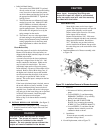
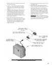
S. BURNERS SUPPLIED BY BURNHAM utilize
a burner disconnect harness that is pre-wired into the
burner junction box and primary control. Packed in the
canopy carton is the mating burner disconnect junction
assembly and mounting hardware for use with these
burners.
If you are using a burner with the disconnect harness,
complete the following assembly instructions for
mounting the mating burner disconnect junction box,
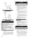
see Figure 10.


