25
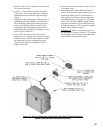
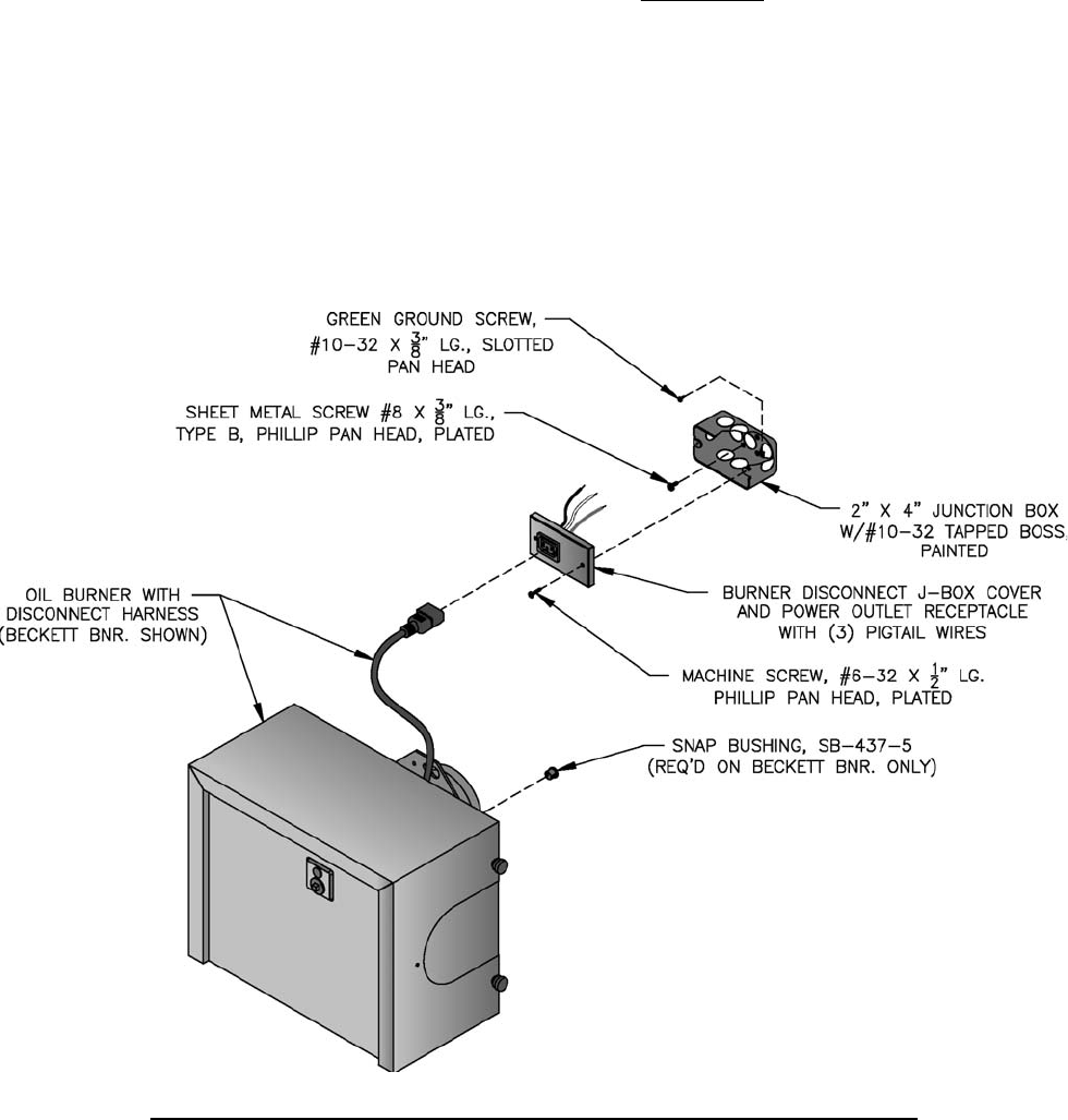
1. Remove (2) #6 x 1/2" lg. machine screws and J-box
cover from junction box.
2. Secure 2" x 4" junction box to jacket front panel
with (2) #8 x 3/8" lg. sheet metal screws using pre-
punched holes below tridicator or pressure gauge
tapping.
3. Complete the fi eld wiring phase of Paragraphs N &
O (Beckett), P (Carlin 102CRD), Q (Carlin Elite
EZ) or R (Riello) Install end of harness from low
water cut-off (LWCO), R8239A Control Center
or Aquastat Control into appropriate knockout of
burner disconnect junction box according to source,
refer to Figures 1A thru 1D.
4. Use wire nuts to connect wires from control or
power source to (3) pigtail wires connected to spade
terminals on rear of power outlet receptacle. Make
the connections as shown in appropriate wiring
diagram based on boiler confi guration, refer to
Figures 19 thru 23F.
5. Secure J-box cover to junction box with (2) #6 x ½"
lg. machine screws.
6. Insert mating end of burner disconnect harness
(power cord) into power outlet receptacle on J-box.
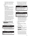
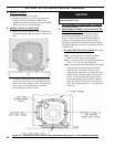
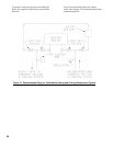
7. Install snap bushing into 7/16" diameter hole in
upper right corner of burner enclosure back plate
on all Beckett burners, see Figure 10. On certain
builds, 18/2 wire from L4006A Aquastat Control
mounted in rear heater will pass through this snap
bushing and connect to "T-T" terminals on primary
control, refer to Figures 20 and 21.
IMPORTANT: Remove (cut) jumper resistor on
R7184P Primary Control to activate "T-T" terminals
when making a direct connection from thermostat
and/or tankless heater aquastat control.
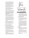
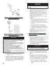
Figure 10: Burner Disconnect Junction Box with Power Outlet Receptacle
(Mated to Burners with Disconnect Harness)


